
Concrete production plant

a production plant and concrete technology, applied in the field of concrete production devices and processes, can solve the problems of imposing considerable logistic constraints, occupying a large amount of space, and complicating maintenance of the plant,

Inactive Publication Date: 2013-10-22
CHRISTIAN CONTAMIN
View PDF8 Cites 0 Cited by
  • Summary
  • Abstract
  • Description
  • Claims
  • Application Information

AI Technical Summary

Benefits of technology

The present invention allows for on-site production of concrete while limiting the space needed for the production plant. A single silo is used without the need for multiple piles of aggregate, reducing space requirements. The large aggregates are pushed to the edges of the silo and withdrawn last, which can create mixing inhomogeneity but is necessary for achieving the desired consistency of the concrete. Overall, this patent enables more efficient and effective concrete production.

Problems solved by technology

This type of plant also takes up a very large amount of space owing to the presence of the storage tanks.
Moreover, the storage tanks must be protected from moisture, thereby complicating their maintenance.
This second solution imposes considerable logistic constraints since the delay before using the concrete contained in the truck mixer is limited and the organization of the work on the work site is determined by the arrival of the trucks.

Method used


Image

  • Concrete production plant
  • Concrete production plant
  • Concrete production plant

Examples


first embodiment

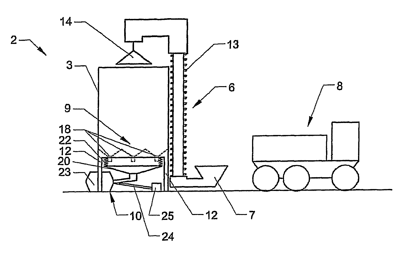
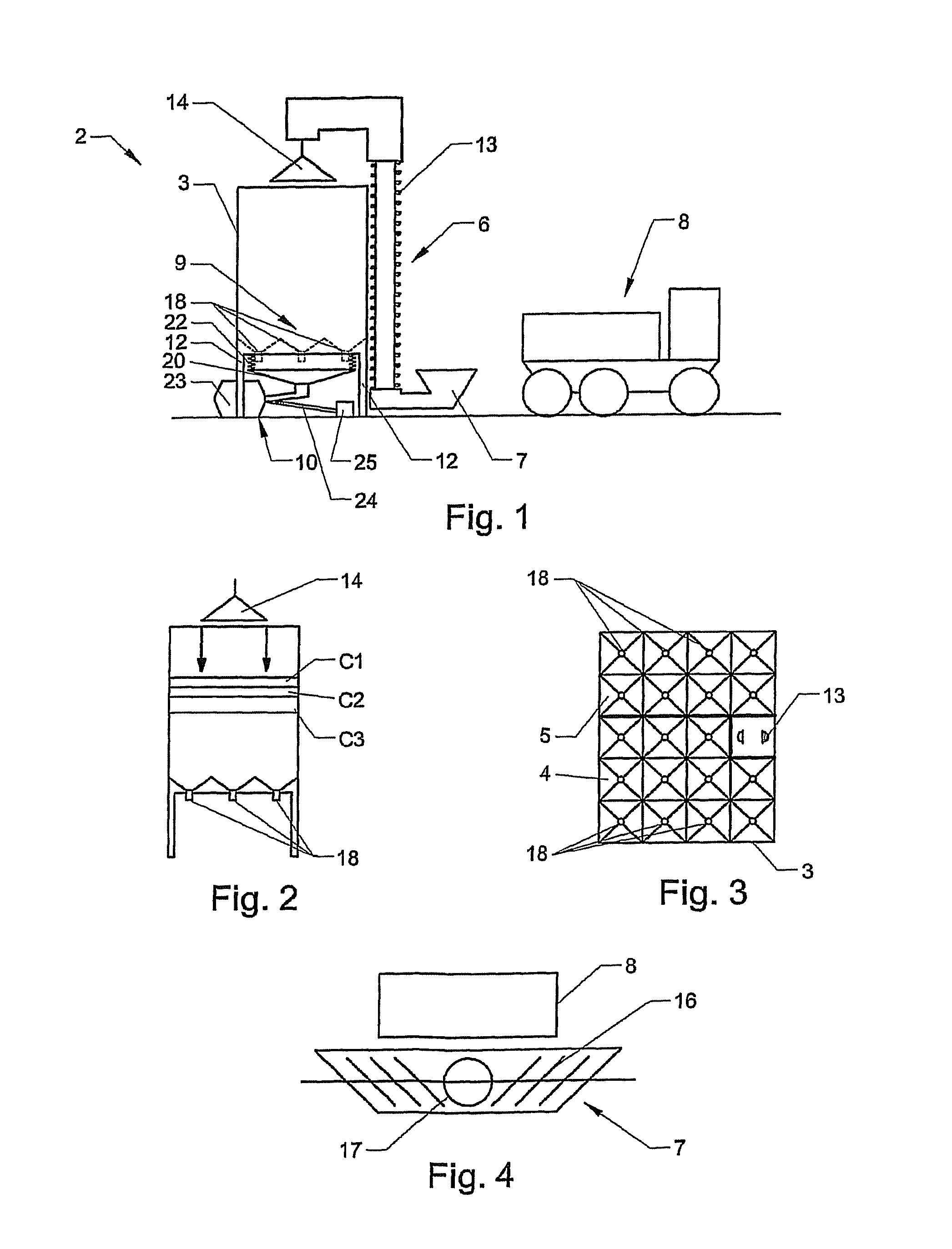
[0101] the means 9 for withdrawing the mixture contained in the silo 3 include a number of openings 18 distributed on the lower wall 19 of a compartment 4, 5 over the cross section of the latter, at the bottom of conical cells.

[0102]This arrangement makes it possible to withdraw, in the lower part of the compartment 4, 5, small doses at points distributed over the cross section of the compartment 4, 5 consecutively and repetitively, in succession on each of the withdrawal openings 18 so as to lower the level of the mixture in a regular fashion.

[0103]Thus, no mixture cone forms as in the hoppers of the prior art, thereby preventing the segregation phenomenon.

[0104]The means 10 for mixing the dry mixture with water comprise a metering hopper 20 for collecting the dry mixture extracted from a compartment 4, 5 of the silo 3 via the withdrawal means 9, the hopper being located beneath the openings 18.

[0105]The weighing means 22 associated with the hopper 20 may be of limited precision, s...

second embodiment

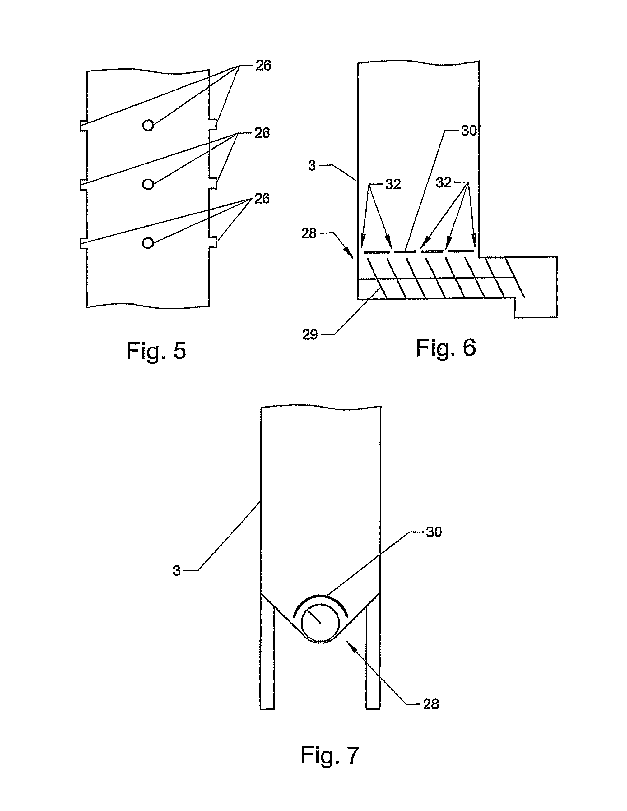
[0112] shown in FIG. 5, the withdrawal means 26 include a set of openings for taking materials on the sides of the compartment 4, 5 at several different heights on one or more faces, with closure means controlled by level according to the height of the mixture inside the silo 3.

third embodiment

[0113] shown in FIG. 6, withdrawal means 28 comprise an endless screw 29, advantageously protected over its upper part by an apertured closure plate 30 so as to limit the load on the screw and thus create three or four points at which this screw is fed via the openings 32 in the plate.


PUM

PropertyMeasurementUnit
temperatureaaaaaaaaaa
widthaaaaaaaaaa

Abstract

The present disclosure allows concrete to be produced on the work site, as and when required, and to limit the space occupied by the production plant.

Description

FIELD OF THE INVENTION[0001]The present disclosure relates to a concrete production device and process.BACKGROUND[0002]Concrete is generally produced from the following components:[0003]aggregates, comprising sand and gravel, the particle sizes of which can vary according to the desired grade of the concrete;[0004]cement;[0005]one or more optional admixtures; and[0006]water.[0007]To produce the concrete, it is known to use a production plant installed on the work site where the concrete is intended to be used.[0008]This plant comprises:[0009]sand and gravel storage containers associated with a shelf for withdrawing the aggregates from each storage container;[0010]at least one silo for storing the cement;[0011]optionally, another silo intended to receive fly ash or filler to be added to the mixture; and[0012]optionally, another storage container for a liquid admixture.[0013]At the moment of use, the concrete is produced by mixing the components with water.[0014]It is imperative to me...

Claims


Application Information

Patent Timeline
Patent Type & Authority Patents(United States)
IPC IPC(8): B28C5/12
CPCB28C7/0076B28C7/0481
Inventor CONTAMIN, CHRISTIANCONTAMIN, HENRI
Owner CHRISTIAN CONTAMIN
Learn More