Oversize metal wood with power shaft

a metal wood and power shaft technology, applied in the field of oversize metal wood with power shafts, can solve the problems of heat distortion of the face wall and rear clubhead, failure to achieve the effect of distributing more energy to the ball, and increasing the distance of the ball

Inactive Publication Date: 2006-07-11
KARSTEN MFG CORP
View PDF14 Cites 30 Cited by
  • Summary
  • Abstract
  • Description
  • Claims
  • Application Information

AI Technical Summary

Benefits of technology

[0085]According to the present invention, the face walls in these clubheads is caused to fully recover prior to ball impact thereby imparting more energy to the ball and increasing ball distance travel. More specifically, one primary object of the present invention is to provide a jumbo clubhead. In excess of 250 cm3, constructed of thin walls, less than 0.125″ in thickness, of a hard alloy with a low modulus relative to steel, with a power shaft integral with the head, that causes the face wall to rebound fully at ball impact before the ball leaves the club face.

Problems solved by technology

While others have attempted supports for other purposes such as face reinforcement and club sound or feel, they have not been successful because these clubs are either not possible to manufacture, or will fail under the rigors of a 100 to 150 ft. / sec. impact velocity against a golf ball.
While welding similar metals is certainly not a new concept, it is not possible to weld, for example, a 0.625 inch diameter shaft with a 0.035 to 0.049 inch wall thickness directly to the club head face wall and rear wall because the face wall and rear wall, because of their large areas, require higher heating and welding temperatures resulting in heat distortion of the face wall and rear clubhead.

Method used


Image

  • Oversize metal wood with power shaft
  • Oversize metal wood with power shaft
  • Oversize metal wood with power shaft

Examples


Embodiment Construction

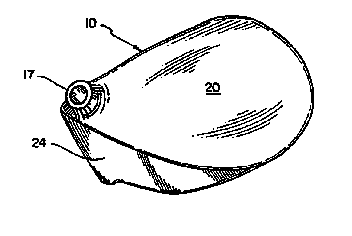
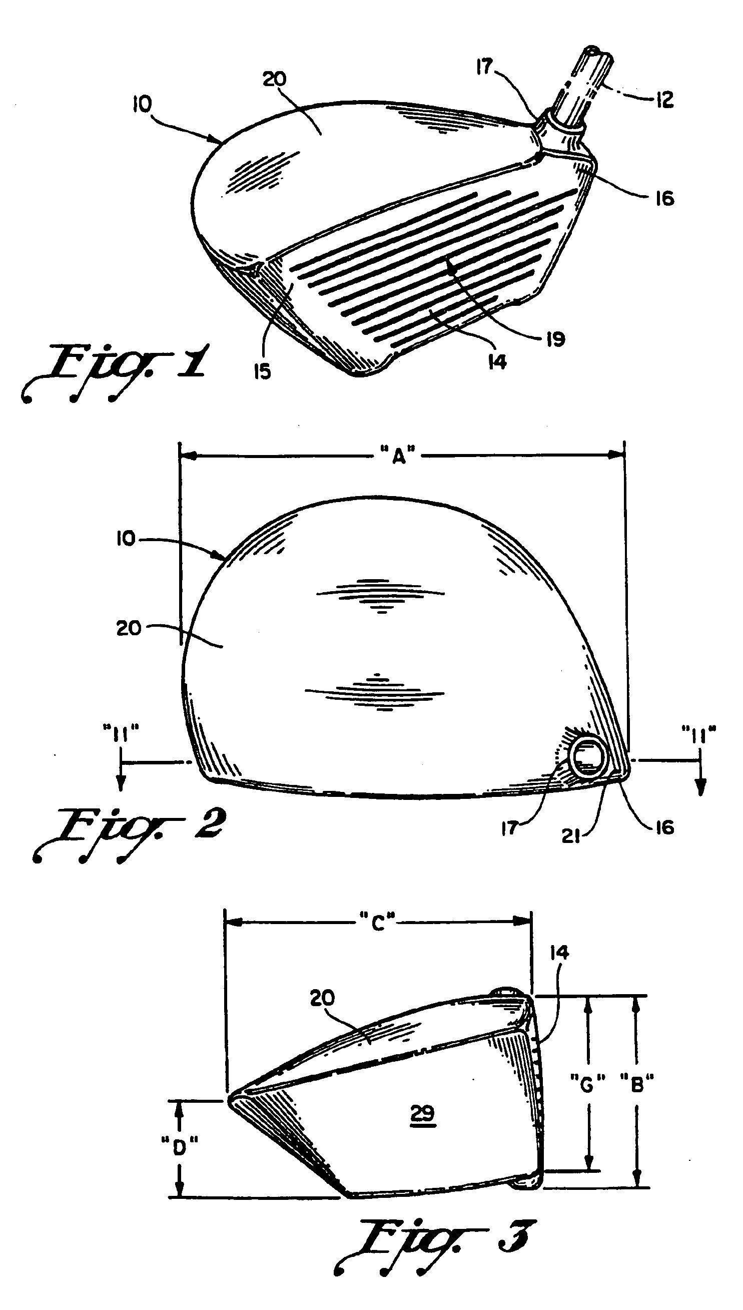
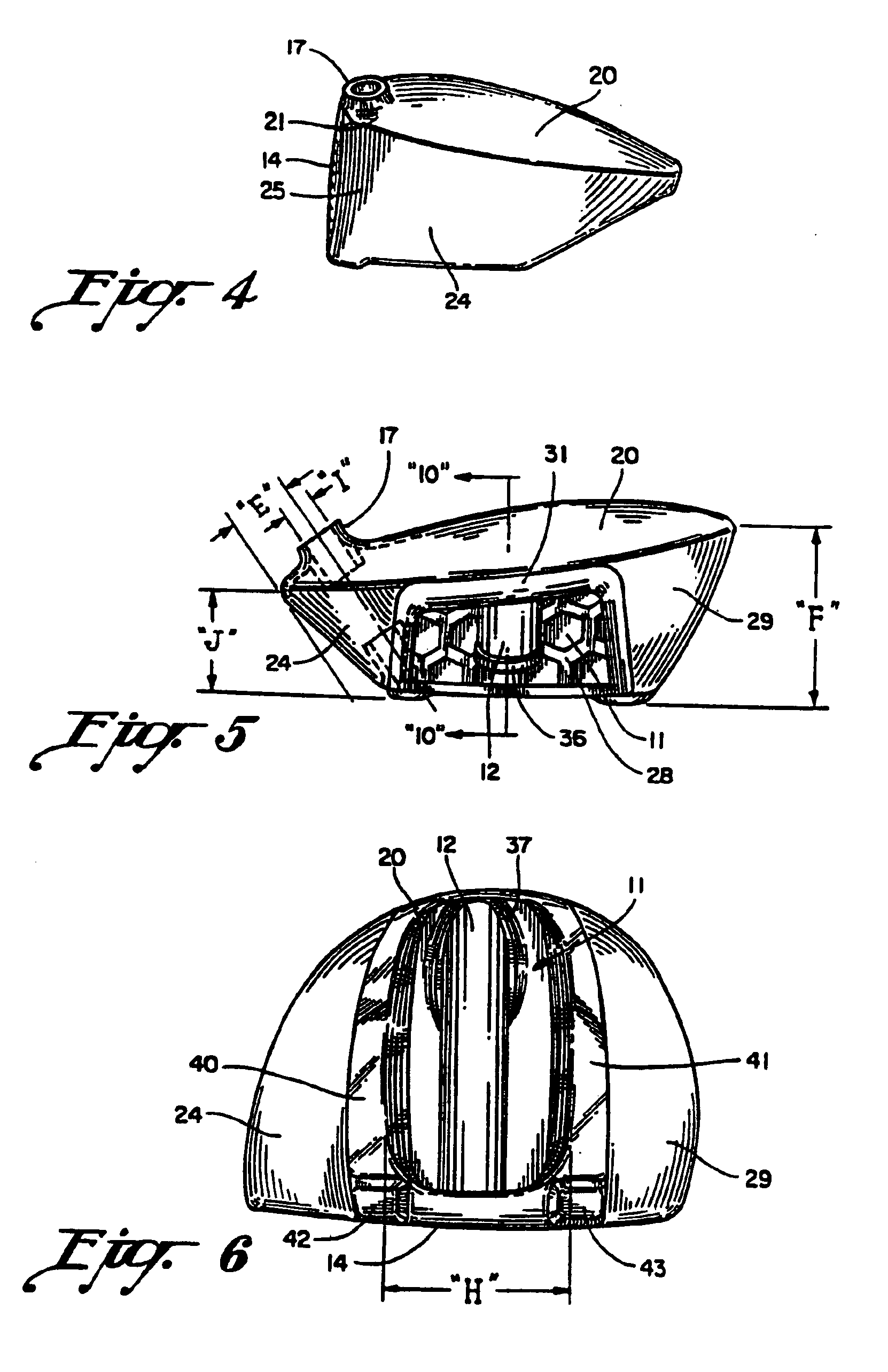
[0103]Referring to the drawings and particularly FIGS. 1 to 8, a clubhead 10 is illustrated which takes the general configuration of what is termed a “metal wood” in the golf industry, and as seen in FIG. 1, is implanted with a shaft 12 shown only in fragmented form which carries at its upper end a conventional grip. A golf club as defined in the present invention includes a clubhead with shaft 12 fixed therein which carries the shown grip at its upper distal end.

[0104]Many of the views in the present drawings including FIGS. 2, 3, 4, 5, 6, 7, 8, 9, 10, 11, 14, 15, 16, 17, and 18 are shown approximately to scale and in fact are about 5 to 10% smaller than a 1—1 scale.

[0105]The clubhead 10 has an included volume of 260 cm.3, but could range from 230 to 300 cm.3. “Included” volume is defined as the volume encompassed to the outermost walls of the clubhead that includes recessed areas that are not actually enclosed by walls such as a bottom wall cavity.

[0106]The clubhead 10 is construc...


PUM


Abstract

A wood-type golf club having an enlarged club head in the range of 250 to 300 cm.3 constructed of a material lighter than steel to maintain the total club head weight within normal limits including the weight of novel power shaft according to the present invention. The club head, without the power shaft, is approximately 175 gms. and the power shaft weighs approximately 25 gms., so the total club head weight is approximately 200 gms. and within normal limits. The power shaft, integral with the rear of the ball striking face wall at its forward end and integral or cast into the rear of the club head at its rear end, while reinforcing the ball striking face wall, increases the resonant frequency of the face wall to synchronize face wall rebound to the player's swing speed. Face wall resonant frequency is varied by changing the size and weight of the power shaft.

Description

BACKGROUND OF THE PRESENT INVENTION[0001]Investment casting techniques innovated in the late 1960s have revolutionized the design, construction and performance of golf club heads up to the present time. Initially only novelty putters and irons were investment cast, and it was only until the early years of the 1980s that investment cast metal woods achieved any degree of commercial success. The initial iron club heads that were investment cast in the very late 1960s and early 1970s innovated the cavity backed club heads made possible by investment casting which enabled the molder and tool designer to form rather severe surface changes in the tooling that were not possible in prior manufacturing techniques for irons which were predominantly at that time forgings. The forging technology was expensive because of the repetition of forging impacts and the necessity for progressive tooling that rendered the forging process considerably more expensive than the investment casting process and...

Claims


Application Information

Patent Timeline
Patent Type & Authority Patents(United States)
IPC IPC(8): A63B53/04A63B53/08A63B53/06
CPCA63B53/04A63B53/0466A63B53/06A63B2053/0408A63B2053/0412A63B2053/0416A63B2053/045A63B2209/00A63B2053/0458A63B2053/0454A63B2053/0433A63B53/0412A63B53/0454A63B53/0458A63B53/045A63B53/0408A63B53/0416A63B53/0433A63B60/0081
Inventor ALLEN, DILLIS V.
Owner KARSTEN MFG CORP
Why Eureka
Try Eureka