Check patentability & draft patents in minutes with Patsnap Eureka AI!

Connector

A connection device and connector technology, which is applied in the direction of two-part connection device, parts of connection device, connection, etc., can solve the problem of easy change of distance

Inactive Publication Date: 2008-01-02
SONY CORP
View PDF9 Cites 0 Cited by
  • Summary
  • Abstract
  • Description
  • Claims
  • Application Information

AI Technical Summary

Problems solved by technology

[0023] In the above connecting device, the axial distance between the end face of the optical cable and the optical element on the side of the plug hole is also easy to change, and the change in signal transmission characteristics cannot be ignored, and there are also problems in characteristics.

Method used


Image

  • Connector
  • Connector
  • Connector

Examples


Embodiment Construction

[0065] The implementation form of the connection device of the present invention will be described in more detail below with reference to the accompanying drawings.

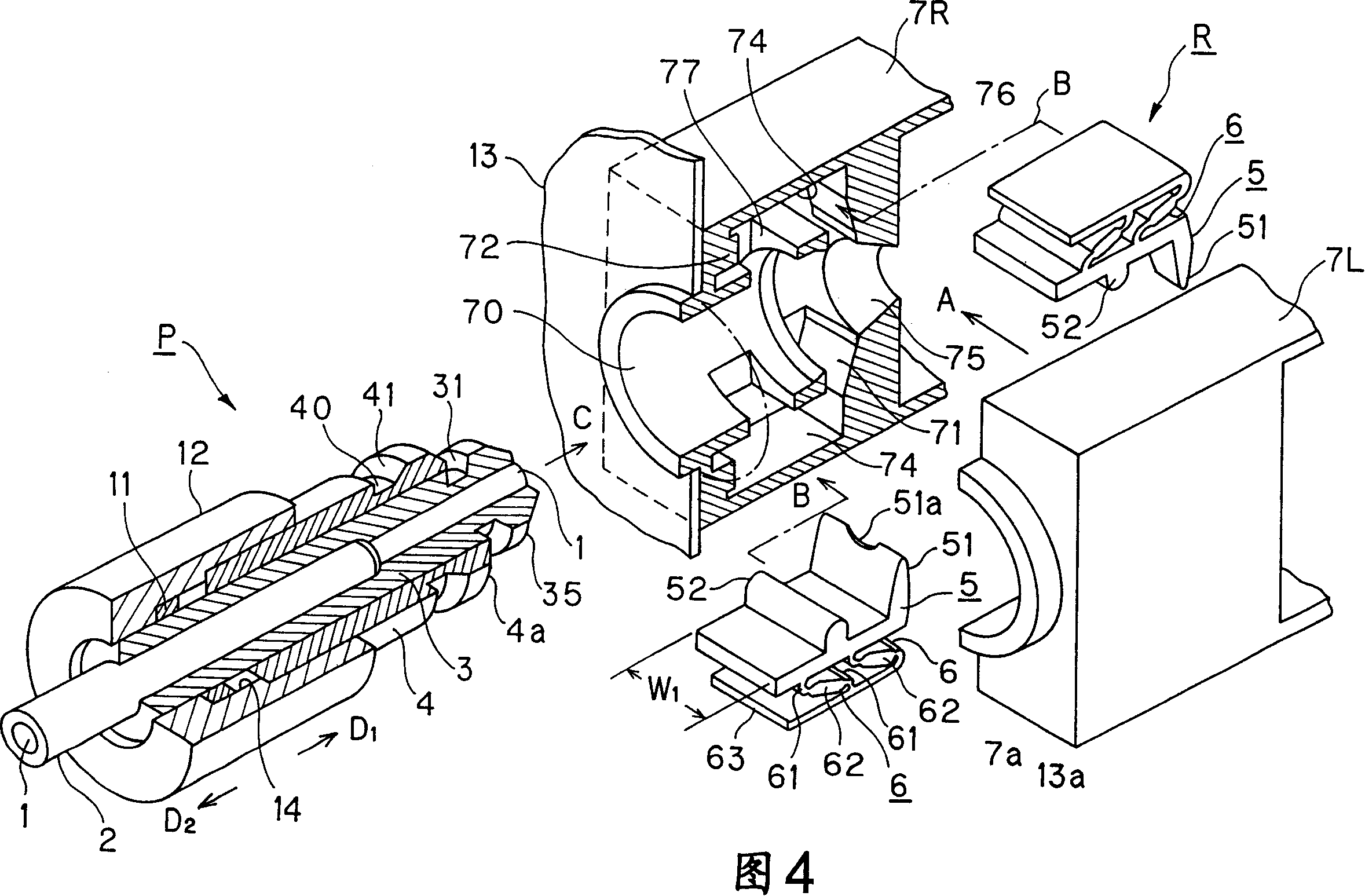
[0066] As shown in FIG. 4, the connecting device of the present invention is constituted by a plug part P and a receptacle part R as a receptacle thereof.

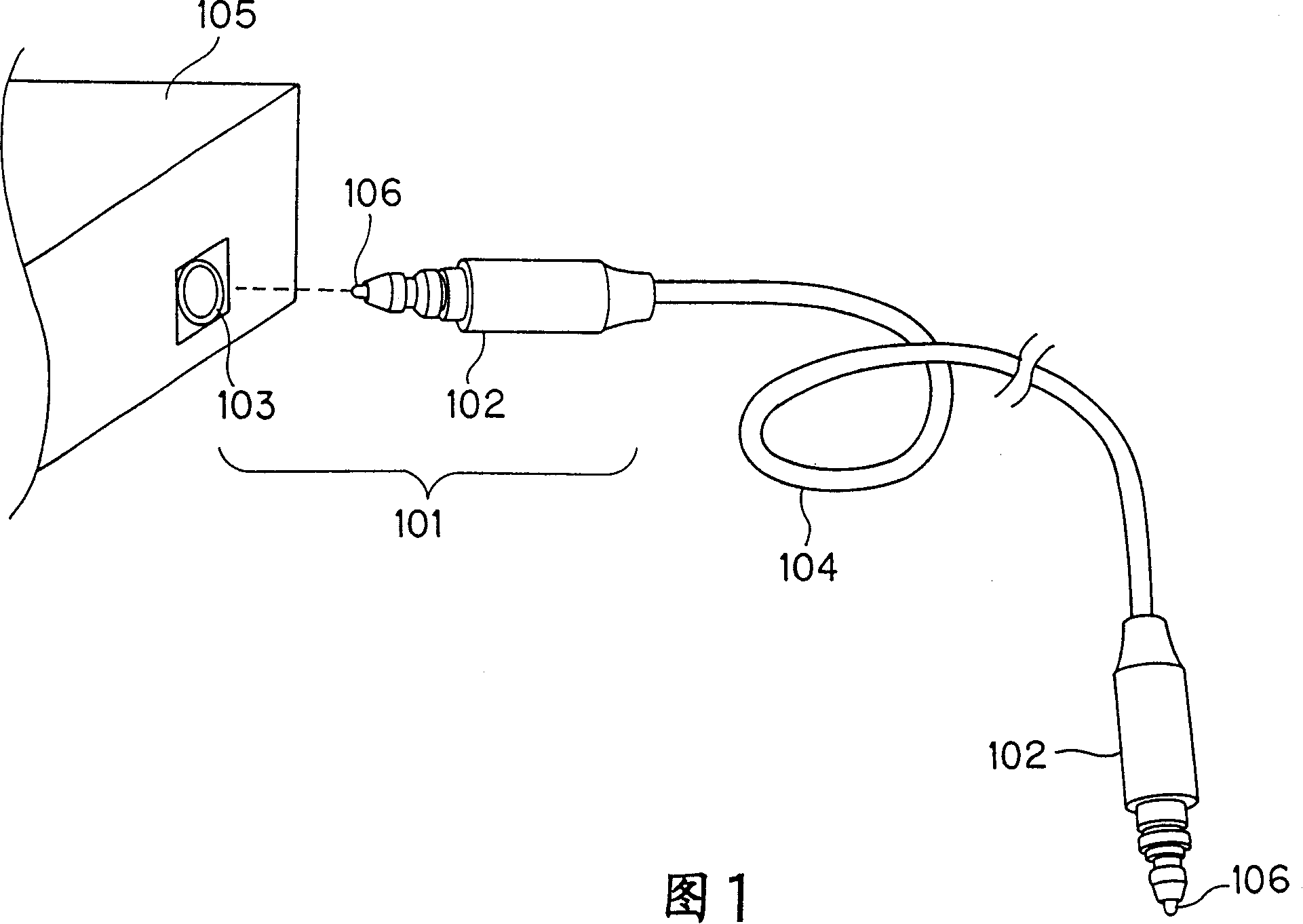
[0067] The plug portion P is attached to, for example, an end portion of the optical fiber cable 2 capable of transmitting signals, and the receptacle portion R is attached to, for example, a board 13 on the back side of the electronic device.

[0068] In such a connection device, by inserting the plug part P into the plug insertion hole 70 provided in the center part of the front side of the socket part R in the direction of the arrow C in FIG. The optical fiber 1 of the optical fiber cable 2 and the optical element 1a arranged in the equipment. An optical fiber may be arranged in the device instead of the optical element 1a, and signals may be transmitted ...


PUM


Abstract

A connector comprising a plug part (P) having a connector plug (3) provided at the end of a signal cable, and a receptacle part (R) for receive the plug part (P), wherein the plug part (P) comprises an unlocking member (4) supported on the outer circumferential surface of the connector plug (3) movably in the axial direction of a cable (2) and fixed with a knob part (12), the plug part (P) capable of being inserted / removed into / from the receptacle part (R),and a member (5) contained in the receptacle part (R) and engaging with the connector plug (3) to lock the plug part (P) is controlled by the axial movement of the unlocking member (4) in the axial direction of the cable (2) through cam parts (40, 41) provided on the outer circumferential surface of the unlocking member (4) thus locking or unlocking the connector plug (3) inserted into the receptacle part (R).

Description

technical field [0001] The present invention relates to a connection device for connecting electronic equipment and a signal cable, in particular to a connection device having a connection plug and a connection plug hole for connecting a signal cable to an electronic device by inserting the connection plug into the connection plug hole . Background technique [0002] In the past, when connecting a plurality of electronic devices so that signals can be transmitted and received, dedicated signal cables were used, and connectors were used to connect the signal cables to the devices. Such a connection device generally connects a signal cable to an electronic device by inserting a plug or a socket attached to an end of the signal cable into a socket or a plug provided on the device side, for example. [0003] In addition, in recent years, signal cables used for connection of various electronic devices include not only electric signal cables known in the past but also optical sig...

Claims


Application Information

Patent Timeline
Patent Type & Authority Patents(China)
IPC IPC(8): G02B6/38G02B6/42H01R13/629H01R13/46H01R24/14H01R13/627
CPCH01R13/6275H01R13/20
Inventor 安田信行
Owner SONY CORP
Features
  • R&D
  • Intellectual Property
  • Life Sciences
  • Materials
  • Tech Scout
  • Unparalleled Data Quality
  • Higher Quality Content
  • 60% Fewer Hallucinations
Learn More