
Field electrode metal semiconductor field effect transistor

A technology of transistors and field electrodes, applied in the field of gallium arsenide field effect transistors, which can solve problems such as limiting the conduction state or maximum current

Inactive Publication Date: 2008-01-09
COBHAM DEFENSE ELECTRONICS SYST CORP
View PDF7 Cites 0 Cited by
  • Summary
  • Abstract
  • Description
  • Claims
  • Application Information

AI Technical Summary

Problems solved by technology

Although it is effective for increasing the breakdown voltage, the additional length of the channel (in the direction of source-drain conduction) introduces additional resistance into the source-drain path, and this additional resistance, in turn, tends to limit the on-state or maximum current

Method used


Image

  • Field electrode metal semiconductor field effect transistor
  • Field electrode metal semiconductor field effect transistor
  • Field electrode metal semiconductor field effect transistor

Examples


Embodiment Construction

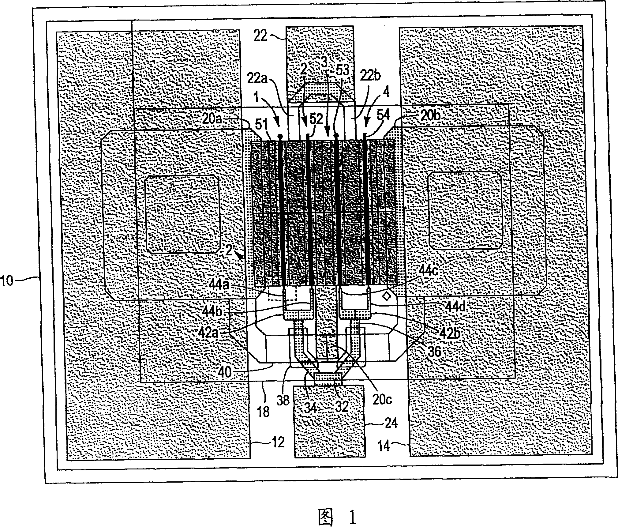
[0021] FIG. 1 is a plan view of a planar transistor according to an aspect of the present invention. In FIG. 1, the chip on which the FET 8 is mounted is indicated by reference numeral 10, and areas 12 and 14 indicate a ground potential plane for on-wafer microwave measurements. In regions 12 and 14 , metallization 20 a , 20 b , 20 c represent source conductors, which are electrically connected in parallel by conductive vias shown at 40 . In FIG. 1 , the drain electrode, contact or bonding pad is indicated by reference numeral 22 , and the gate electrode, contact or bonding pad is indicated by reference numeral 24 .

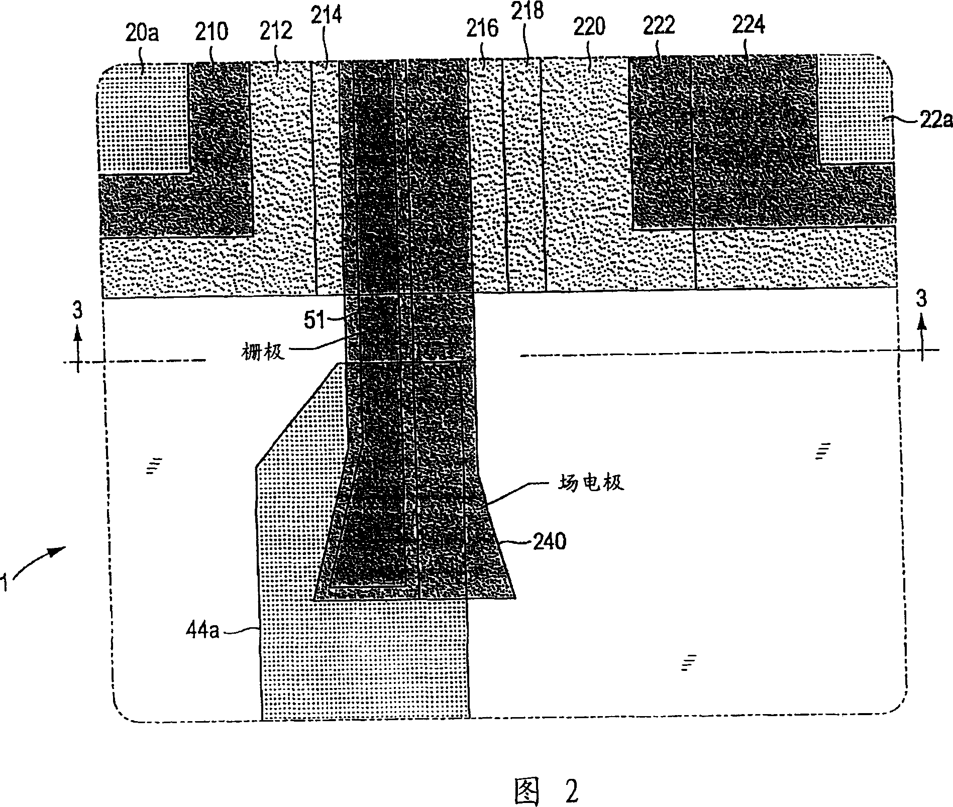
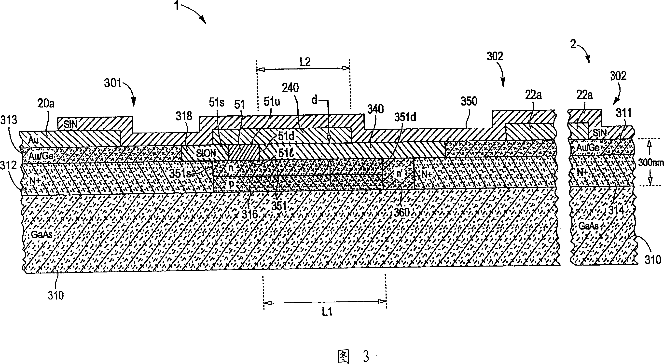
[0022] FET 8 of FIG. 1 has four parallel individual FET elements, which are indicated by reference numerals 1, 2, 3 and 4, respectively. These individual FET elements are described in detail with reference to FIG. 3 .

[0023] In FIG. 1, drain pad 22 is connected to the drain region of FET 8 through metallization 22a and 22b. Gate pad 24 is connected in series...


PUM


Abstract

A planar MESFET transistor includes a plurality of FET elements. Each FET element includes a doped planar channel, and source and drain coupled to the ends of the channel. A gate conductor extends over a portion of the channel at a location lying between the source and drain, a first predetermined distance from the drain. A field plate is connected to the gate conductor, and extends toward the drain a second predetermined distance, isolated from the channel except at its gate conductor connection by a dielectric material.

Description

technical field [0001] The present invention relates generally to semiconductor devices and, more particularly, to gallium arsenide (GaAs) field effect transistors (FETs). Background technique [0002] GaAs metal-semiconductor field-effect transistors (MESFETs) are existing devices used to provide microwave frequency amplification, high-speed digital switching, and various other functions. The use of microwave devices in satellite-based and wireless communications has grown rapidly in recent years. In these applications, there is a very high power capacity per unit transistor surface area, expressed in W / mm 2 Said that MESFETs have a vast market. Due to the increased power capacity or output of the transistor, a single transistor is able to deliver the power provided by multiple transistors in previous generations, which provides cost, volume and weight savings. The greater the power capacity of a transistor, the wider its potential applications and the larger its potenti...

Claims


Application Information

Patent Timeline
Patent Type & Authority Patents(China)
IPC IPC(8): H01L29/772H01L21/28H01L21/338H01L27/06H01L29/06H01L29/40H01L29/812
CPCH01L27/0605H01L29/402H01L29/812H01L29/772
Inventor 戴恩·C·米勒因德·J·巴尔爱德华·L·格里芬
Owner COBHAM DEFENSE ELECTRONICS SYST CORP
Learn More