Automatic-boosting reciprocating pump

A reciprocating pump, automatic technology, applied in the field of reciprocating pumps, can solve problems such as insufficient boost ratio, easy leakage, insufficient displacement, etc., to achieve uniform flow, increase boost level, and increase displacement level.

Active Publication Date: 2008-09-17
张志英 +1
View PDF7 Cites 0 Cited by
  • Summary
  • Abstract
  • Description
  • Claims
  • Application Information

AI Technical Summary

Problems solved by technology

[0006] Aiming at the problems existing in the above-mentioned prior art, the present invention designs a mechanical valve-controlled automatic pressurized reciprocating pump through careful development and multiple tests, which solves the problem of insufficient material supply, displacement, and pressurization in the prior art. Insufficient ratio and easy leakage problems, and reduce costs, improve safety, reliability, stability and mechanism versatility

Method used


Image

  • Automatic-boosting reciprocating pump
  • Automatic-boosting reciprocating pump
  • Automatic-boosting reciprocating pump

Examples


Embodiment

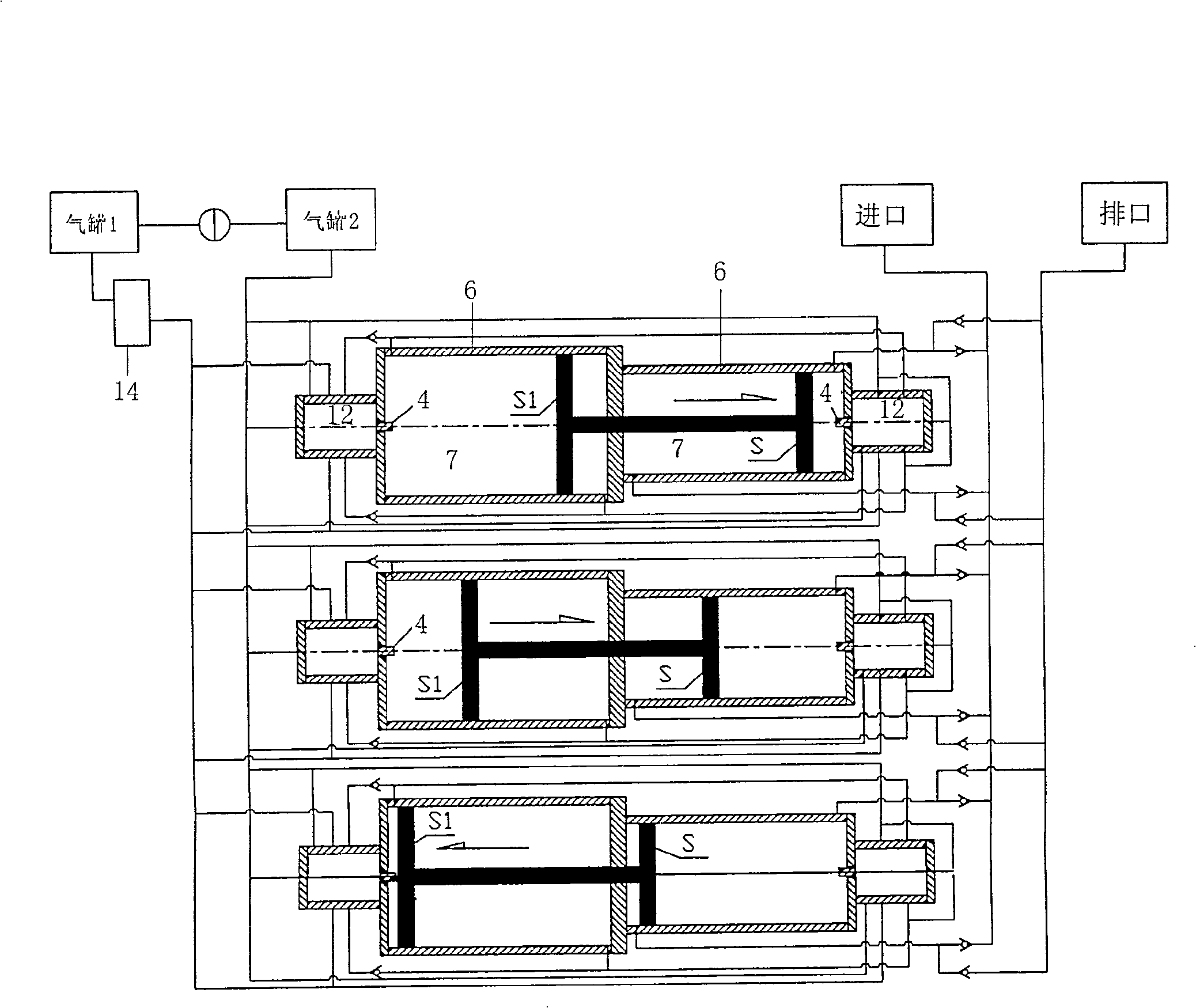
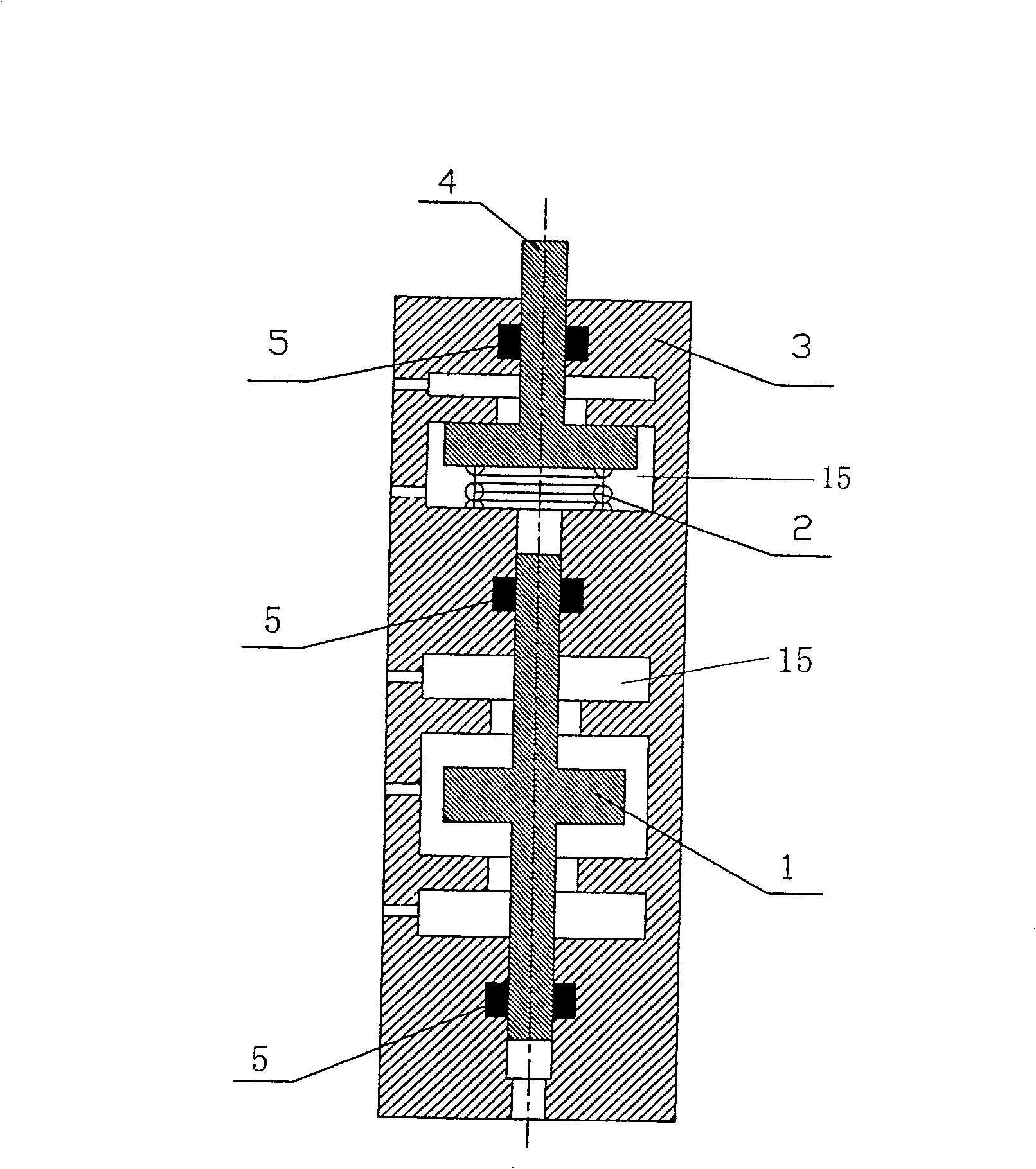
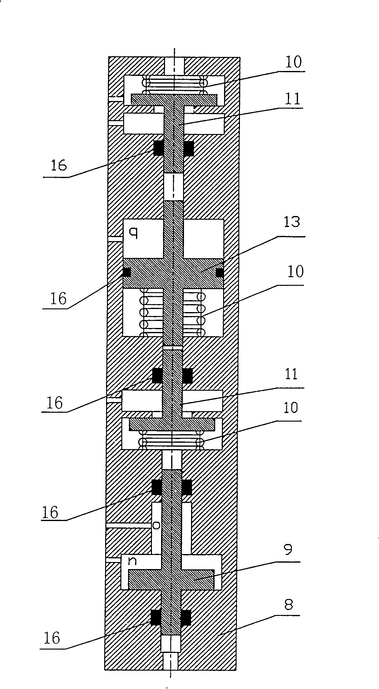
[0028] Below in conjunction with accompanying drawing, specific structure of the present invention is described in detail as follows:

[0029] Such as Figure 1-3 As shown, one of the combined use forms of series and parallel in its working principle: two-stage series and three sets of parallel structure is used as an example for specific description, and three sets of booster reciprocating devices are set, and the booster reciprocating devices are: The two-pole cylinders 6 are connected in series on the same axis line, the pistons of the cylinders 6 are arranged in the cylinder cavity 7, and the two ends of the cylinders 6 connected in series are respectively provided with an automatic control switching direction valve group 12, and the automatic control switching direction One end of the contact 4 of the valve group 12 is arranged at both ends of the cylinder cavity 7, and a spring 2 is arranged between the other end of the contact 4 and the inner cavity 15 of the housing 3 ...


PUM


Abstract

The invention relates to an automatic pressurized reciprocating pump controlled by mechanical valve, comprising a group of pressurized reciprocating device at least. Said pressurized reciprocating device is characterized in that two-pole or multi-pole cylinder is connected in the same axis, automatic controlling switch valve units are set on two ends of cylinder respectively, one end of contact tip in automatic controlling switch valve units and cylinder piston are set in the inner cavity of cylinder. Each group of pressurized reciprocating device is connected in parallel. The invention improves not only pressurized grade but also discharge grade. It is provided with low cost, good sealing, good safety and stability so on.

Description

technical field [0001] The invention relates to a reciprocating pump whose piston can continuously reciprocate, in particular to a mechanical valve-controlled automatic booster reciprocating pump. Background technique [0002] At present, there are precedents at home and abroad for using compressed air or liquid as power to increase the mechanical device for conveying fluid medium through a cylinder or liquid cylinder with two poles connected in series. However, under different usage conditions, the medium to be pressurized and conveyed has a different allowable range of pressure difference at the inlet. During the pressurized conveying process, when the pressure at the inlet exceeds the allowable range, insufficient material supply or displacement Insufficient and other abnormal phenomena, resulting in insufficient displacement when selecting booster equipment specifications, or excessively low front-end pressure due to excessive suction, thus affecting the normal operation...

Claims


Application Information

Patent Timeline
Patent Type & Authority Patents(China)
IPC IPC(8): F04B23/06F04B9/08F04B49/22
Inventor 张志英
Owner 张志英
Why Eureka
Try Eureka