Compressed air energy storage system and method capable of releasing water pumping at constant pressure

A compressed air energy storage and compressor technology, which is applied in the field of physical energy storage, can solve the problems affecting the high efficiency and economy of the compressed air energy storage system, the difficulty of power balance and operation control, and the difficulty in absorbing new energy power generation. , to achieve the effect of high efficiency and economy, stable pressure, and reduced grade requirements

Active Publication Date: 2022-07-12
XIAN THERMAL POWER RES INST CO LTD
View PDF20 Cites 0 Cited by
  • Summary
  • Abstract
  • Description
  • Claims
  • Application Information

AI Technical Summary

Problems solved by technology

[0002] With the increasing proportion of new energy in the power system, such as "large fluctuations in new energy output, great difficulty in power balance and operation control, difficulty in accommodating large amounts of new energy power generation, crowding out conventional power supply space, and accommodating "Prominent contradictions with security" will bring huge challenges to the power system
Compressed air energy storage is one of the must-choice technologies for large-capacity energy storage. However, when compressed air energy storage releases air, the constant factors of pressure instability and low utilization directly affect the efficiency and economy of the compressed air energy storage system.

Method used


Image

  • Compressed air energy storage system and method capable of releasing water pumping at constant pressure
  • Compressed air energy storage system and method capable of releasing water pumping at constant pressure
  • Compressed air energy storage system and method capable of releasing water pumping at constant pressure

Examples


Embodiment Construction

[0031] The present invention will be further described below in conjunction with the accompanying drawings and embodiments.

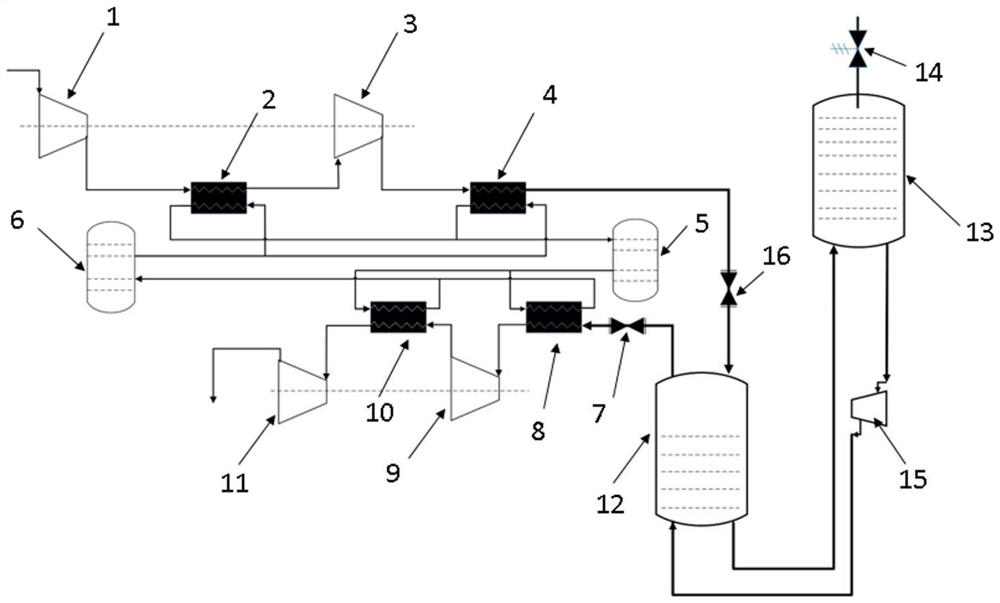
[0032] likefigure 1 As shown in the figure, the compressed air energy storage system of the present invention for pumping water and releasing constant pressure includes an air compression system, a heat storage and heat release system, a temperature rise and expansion system, and a compressed air constant pressure release system, wherein the air compression system includes a first-stage compressor 1 and a Secondary compressor 3, the heat storage and heat release system includes a primary cooler 2, a secondary cooler 4, a heat storage tank 5, a cold storage tank 6, a heater, a primary heater 8 and a secondary heater 10, compressed air The constant pressure release system includes a low-level water tank 12, a high-level water tank 13, and a booster pump 15. The top of the low-level water tank 12 is provided with an air inlet and an air outlet, the bottom o...


PUM


Abstract

The invention discloses a pumping constant pressure release compressed air energy storage system and method.The heat absorption side of a heat storage and release system is connected with the heating side of an air compression system, the heat release side of the heat storage and release system is connected with the heat absorption side of a temperature rise expansion system, an air inlet and outlet is formed in the top of a low-level water tank, and a water inlet and outlet is formed in the bottom of the low-level water tank; a water inlet and a water outlet are formed in the bottom of the high-level water tank, a compressed air outlet of the air compression system is communicated with an air inlet of the low-level water tank and provided with a first adjusting valve, a water outlet of the low-level water tank is communicated with a water inlet of the high-level water tank, and a booster water pump is arranged on a communicated pipeline. And an air outlet of the low-level water tank is connected with an air inlet of the heating expansion system, and a second adjusting valve is arranged on a connecting pipeline. According to the invention, the effect of constant-pressure release in the energy release process can be thoroughly solved, the stored energy is efficiently utilized, high efficiency and economical efficiency are realized, and the method has the characteristics of high safety and high economical efficiency.

Description

technical field [0001] The invention belongs to the field of physical energy storage, and relates to a compressed air energy storage system and method for pumping and constant pressure release. Background technique [0002] With the increasing proportion of new energy in the power system, such as "the output of new energy fluctuates greatly, the power balance and operation control are extremely difficult, the consumption of new energy is difficult when the power generation is large, the space for conventional power is crowded, and the consumption of new energy is difficult. The "prominent contradiction with security" will bring huge challenges to the power system. Compressed air energy storage is one of the necessary choices for large-capacity energy storage technology. However, when the compressed air energy storage system releases air, the constant factors of unstable pressure and low utilization rate directly affect the high efficiency and economy of the compressed air en...

Claims


Application Information

Patent Timeline
Patent Type & Authority Applications(China)
IPC IPC(8): F01K27/00F04D13/02
CPCF01K27/00F04D13/02Y02E70/30
Inventor 姬海民韩伟宋晓辉赵翰辰陆续付康丽
Owner XIAN THERMAL POWER RES INST CO LTD
Why Eureka
Try Eureka