No- wear scissors for hair cut and the like application occasions

A technology of scissors and occasions, applied in the direction of metal processing, etc., can solve the problems of damage, cost of time and expense, unsatisfactory, etc., and achieve the effect of brisk movement

Inactive Publication Date: 2008-10-15
三上昭
View PDF8 Cites 0 Cited by
  • Summary
  • Abstract
  • Description
  • Claims
  • Application Information

AI Technical Summary

Problems solved by technology

Scissors with worn contact areas will not provide the well-running, even and clean cut that they would without wear
Of course, uneven wear of the blades can be repaired, or avoided by regular overhauls, but for these purposes the scissors must often be returned to the manufacturer, at the cost of significant time and expense
Local repair services often prove unsatisfactory or even cause damage

Method used


Image

  • No- wear scissors for hair cut and the like application occasions
  • No- wear scissors for hair cut and the like application occasions
  • No- wear scissors for hair cut and the like application occasions

Examples


Embodiment Construction

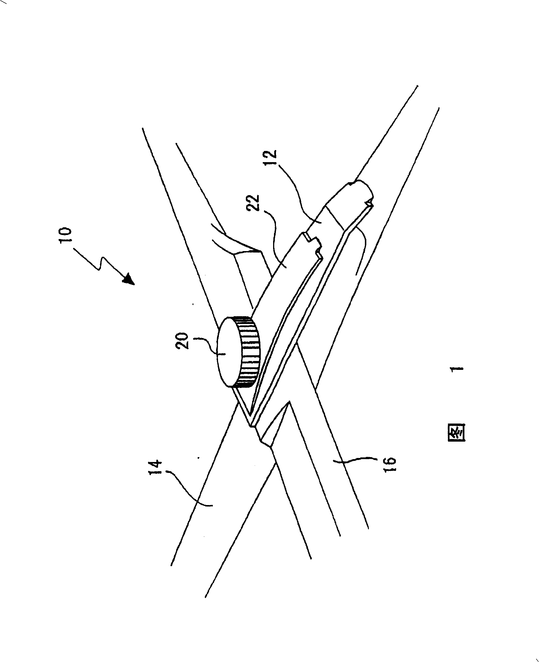
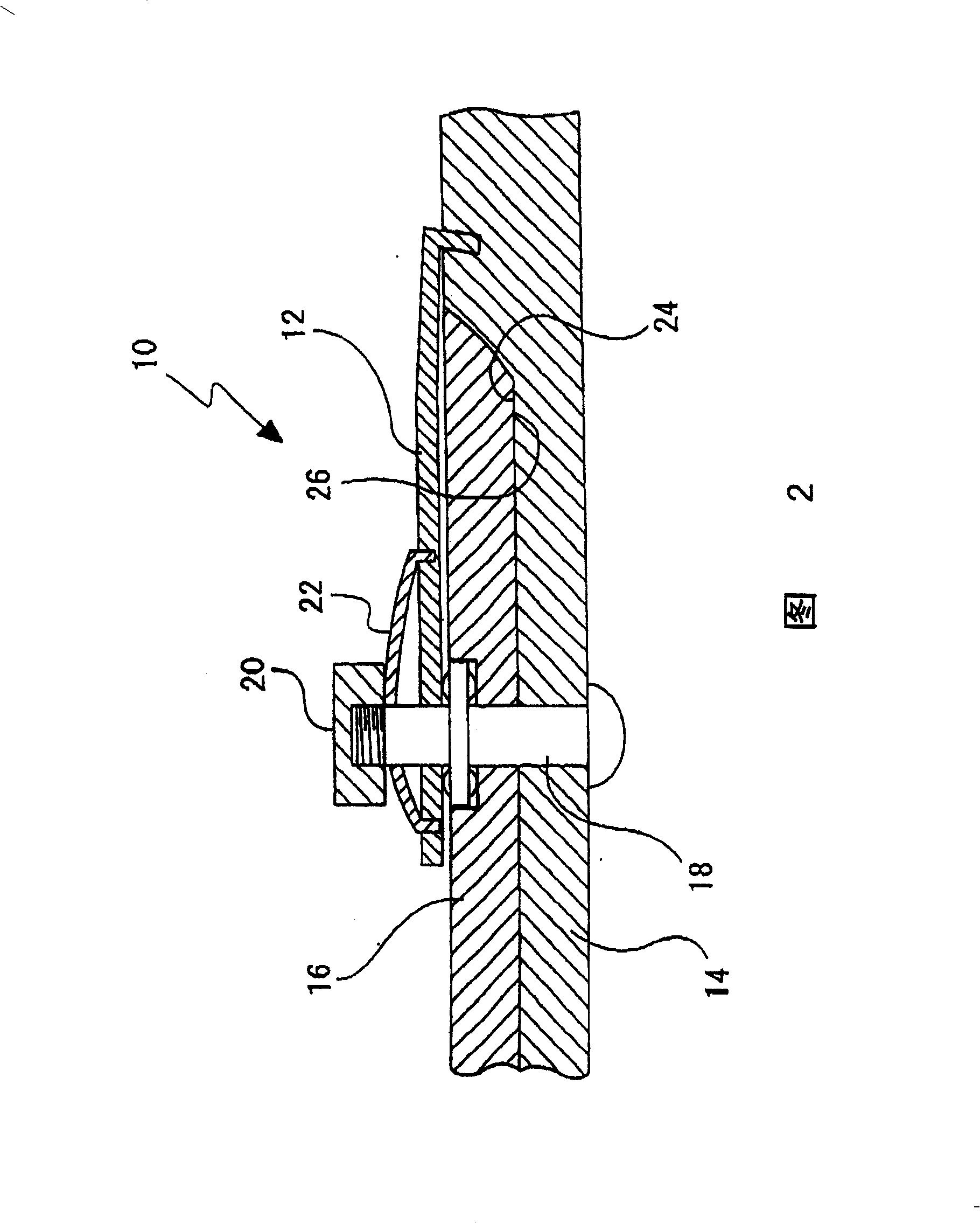
[0026] Careful examination of the above-mentioned prior art spring-assisted scissors according to Japanese Unexamined Patent Publication No. 11-244550 will help to better understand the features and advantages of the disclosed blade scissors. Referring to Figures 1 and 2, prior art scissors 10 have a cantilever spring 12 with a bent end embedded in the handle end of a blade 14, the other end being held against the other blade 16 and drilled. , to fit on a bolt 18 that pivotally connects the two blades 14 and 16 . A cover nut 20 is provided on the fastening bolt 18, and the blades 14 and each other are pressed together by the cantilever spring 12 and an adjusting leaf spring 22.

[0027] Being spring-loaded as described above, the prior art scissors require minimal additional force from the operator to maintain the contact areas 24 and 26 of the blades 14 and 16 in sliding engagement with each other during cutting. Sooner or later, these contact areas 24 and 26 will wear down ...


PUM


Abstract

The pair of cutting blades are pin joined to each other at their terminal webs which are joined to bow handles. A ball bearing is mounted to the pivot pin by way of an antifriction spacer for providing a permanent spacing between the terminal webs in order to prevent the same from abrasion and consequent uneven wear. A clamp is coupled at one end to the pivot pin projecting from one of the terminal webs, and anchored at another end to the other terminal web, in order to bear the component of cutting resistance which tends to spread the pair of blades in opposite directions away from their parallel planes of motion.

Description

technical field [0001] The present invention generally relates to scissors including those articles generally classified as shearing implements. In particular, the present invention relates to non-abrasive, light-acting, long-life scissors suitable for hairdressing salons or barbershops, which allow cutting and trimming of hair using the latest, up-to-date technology for haircutting, although not necessarily limited to this particular application. Background technique [0002] In the simplest form of man-made tool, scissors consist essentially of two blades with handles connected together by a pin in an intermediate position for pivotal movement in two parallel planes. When the handle is closed, the blades or their precise cutting edges slide past each other to provide the cutting action. When cutting, the blades encounter resistance not only in the direction preventing the handles from closing, but also in the direction of opening the pair of blades in opposite directions...

Claims


Application Information

Patent Timeline
Patent Type & Authority Patents(China)
IPC IPC(8): B26B13/28
CPCB26B13/28
Inventor 三上昭
Owner 三上昭
Why Eureka
Try Eureka