Locking quick-change chuck assembly

a quick-release, chuck technology, applied in the direction of manufacturing tools, mechanical equipment, transportation and packaging, etc., can solve the problems of workers, construction workers and carpenters whoregularly change drill bits in numerous types of construction projects, and may not only be inconvenient to change bits, but also dangerous

Inactive Publication Date: 2001-11-22
INSTY BIT
View PDF0 Cites 67 Cited by
  • Summary
  • Abstract
  • Description
  • Claims
  • Application Information

AI Technical Summary

Benefits of technology

0017] The present invention can also be defined as a locking chuck assembly for a tool bit shank of the type which has a circumferential groove disposed thereabout. The chuck assemblyincludes a chuck hub having a forward face and a fixed radial extension. A longitudinal bore isprovided in the hub for receiving the tool bit shank, with the longitudinal bore having aterminating face. A shuttle is disposed in the bore. The shuttle has a bit end, a spring end, aforward lower face and a rearward interim face, and the shuttle is slidable along the longitudinalbore between a rearward position and a forward position. A shuttle spring is disposed betweenthe spring end of the shuttle and the terminating face of the bore, with the shuttle spring acting tobias the shuttle to its forward position. A rear bore extends radially through the hub proximatethe terminating face of the longitudinal bore so as to be in communication with the longitudinalbore, and a shuttle detent ball is disposed in the rear bore so as to engage the shuttle. A frontbore extends radially through the hub proximate the forward face so as to be in communicationwith the longitudinal bore, a

Problems solved by technology

This often causes problems for workers (i.e., construction workers and carpenters) whoregularly change drill bits in numerous types of construction projects.
Changing the bit may not only be inconvenient, but also dangerous.
These awkwardmethods of changing of the bit often result in

Method used


Image

  • Locking quick-change chuck assembly
  • Locking quick-change chuck assembly
  • Locking quick-change chuck assembly

Examples


Embodiment Construction

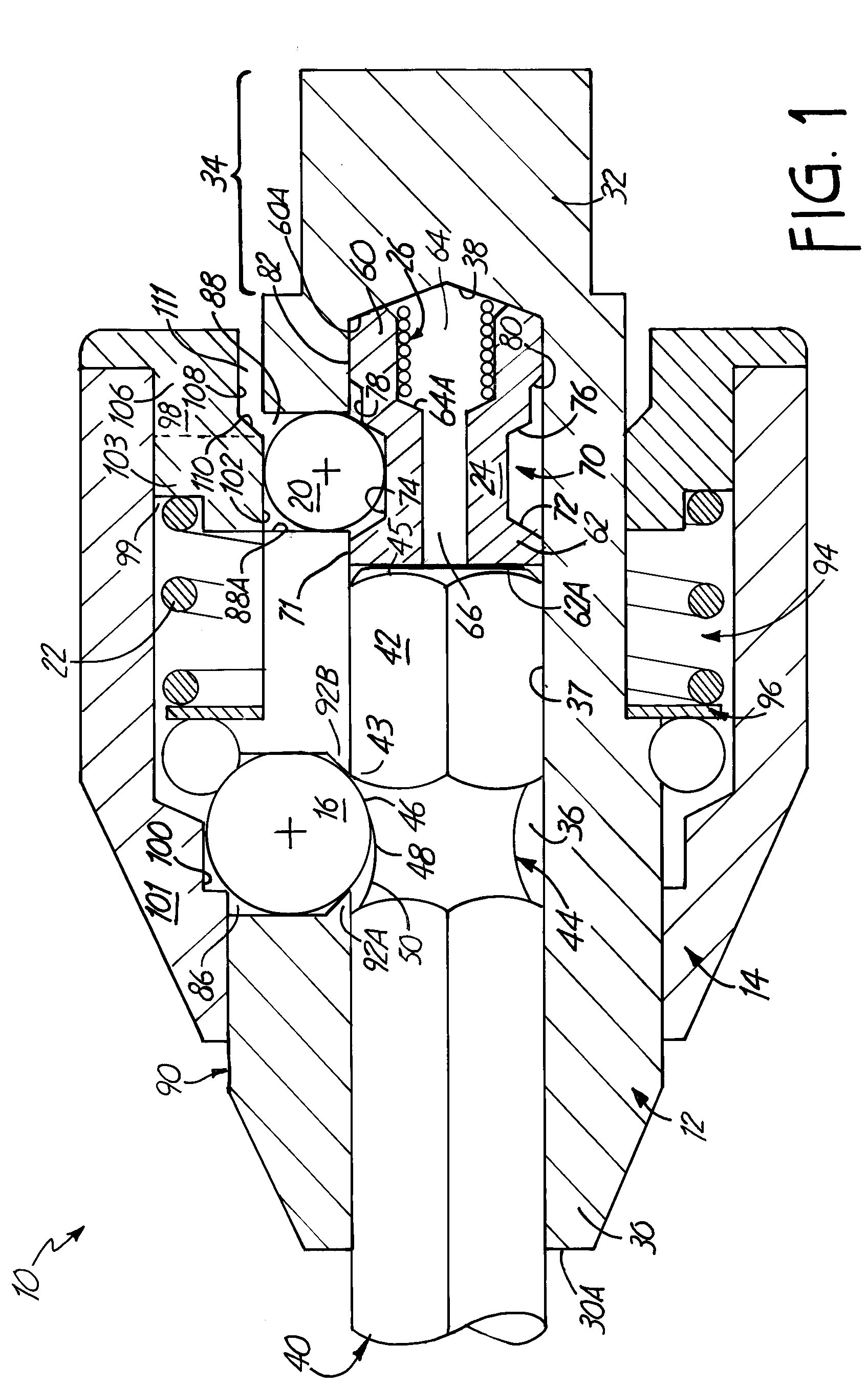
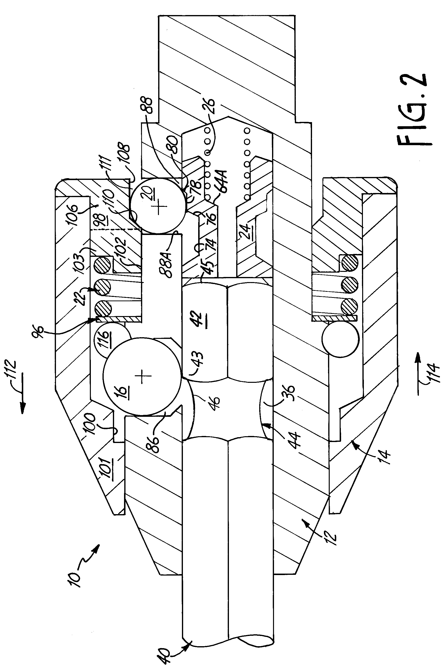
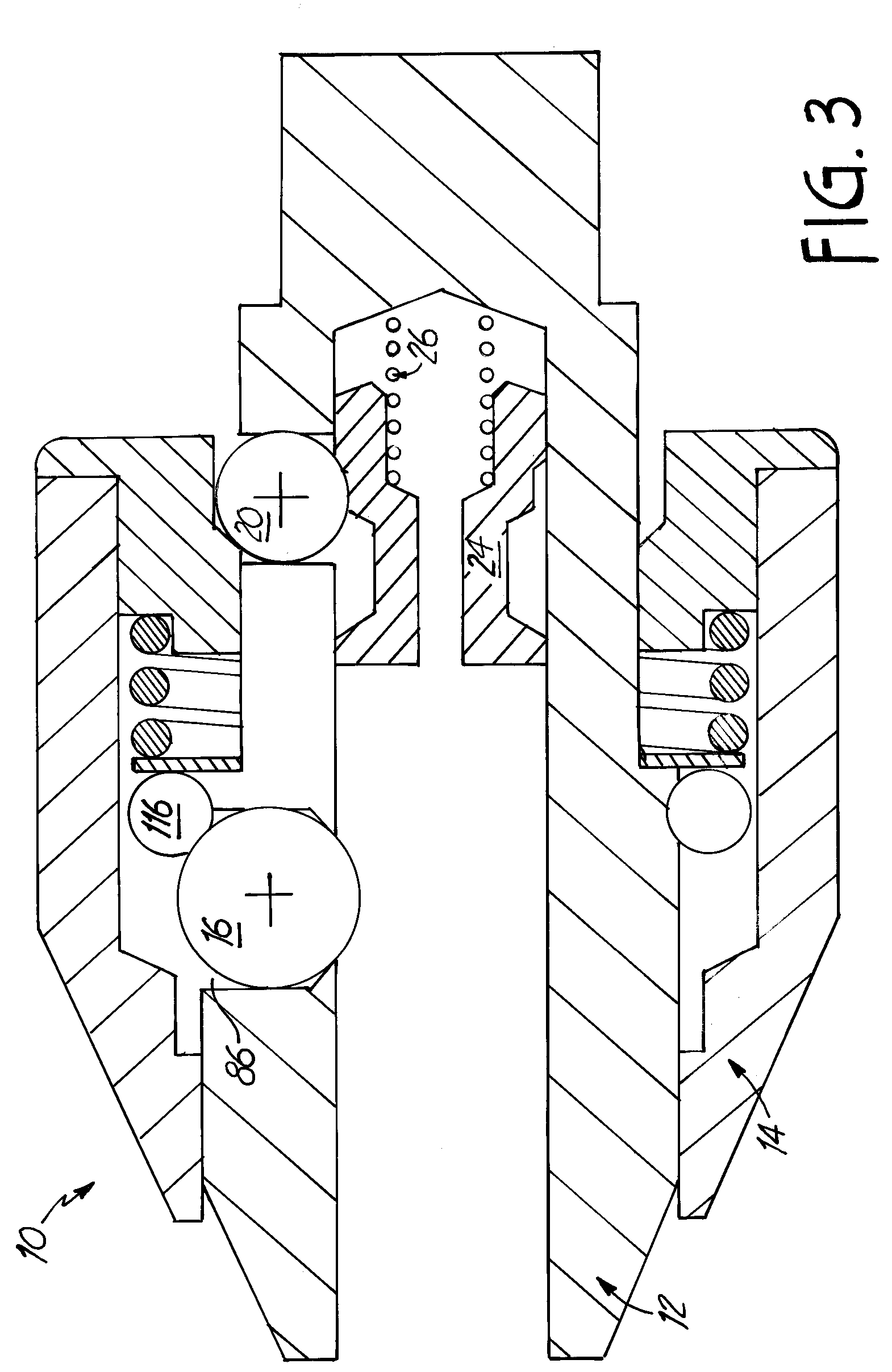
[0034] The present invention is a quick change chuck for a tool bit illustrated generally at 10 in FIG. 1. The chuck 10 includes a chuck hub 12, a sleeve 14, a bit detent ball 16, a shuttle detentball 20, a sleeve spring 22, a shuttle 24 and a shuttle spring 26.

[0035] The chuck hub 12 includes a forward distal end 30 and a driven proximal end 32. The driven end 32 is shaped to form a spindle 34 (typically having a hexagonally shaped cross-section) to provide a connection to the power tool. The forward end 30 terminates in a forwardface 30A. A hexagonal bore 36 extends perpendicularly into the forward face 30A and axiallytowards the driven end 32 of the hub 12. The hexagonal bore 36 is centered in the forward face30A, is substantially aligned along the longitudinal axis of the hub 12 and is shaped to admit astandard quick release tool bit 40. The bore 36 includes an inner wall 37 and terminates in thehub 12 along a terminating face 38. Preferably, the terminating face 38 is generally...


PUM

PropertyMeasurementUnit
Diameteraaaaaaaaaa
Dimensionaaaaaaaaaa

Abstract

<heading lvl="0">Abstract of the Disclosure</heading> The invention is an improvement to a chuck assembly of the type having a chuck hub with a longitudinally extending bore therein the longitudinally extending bore having a closed end, an open end, and a radially extending bit bore in communication with the longitudinally extending bore, and a bit ball movable in the ball bore between a first retracted position out of the longitudinally extending bore and a second engaged position partially in the longitudinally extending bore. The inventive improvement includes a shuttle slidably disposed in the longitudinally extending bore. The shuttle has a first longitudinally extending portion having a first lateral dimension and a second longitudinally extending portion having a second, smaller lateral dimension. The shuttle is movable longitudinally between a first release position and a second lock position. The inventive improvement also includes a compression spring urging the shuttle away from the closed end of the longitudinally extending bore, and a shuttle ball disposed in a radially extending shuttle ball bore in the chuck hub which is in communication with the longitudinally extending bore of the chuck hub. The shuttle ball is movable in the shuttle ball bore between a first retracted position where the shuttle ball contacts the first longitudinally extending portion of the shuttle and a second extended position where the shuttle ball contacts the second longitudinally extending portion of the shuttle.

Description

Cross Reference to Related Applications[0001] This application claims priority from Provisional Application No. 60 / 165,520 filed November15, 1999, for "LOCKING QUICK-CHANGE CHUCK ASSEMBLY" by J. Wienhold.Background of the Invention[0002] This invention relates to chuck assemblies for tool bits and, more particularly to a quick release chuck adapted for releasing the bit from the chuck using one hand.[0003] Tool bits include tools used for drilling, driving, fastener devices such as screws, nuts and bolts, and other work elements requiring rotational motion. The American National StandardsInstitute has a specification for such tools known as ANSI B 107.4-1982 which refers to drivingand spindle ends for portable powered and hand held machines using tool bits. Tool bits inaccordance with the standard have a hexagonally configured shank with a circumferential grooveformed into the shank. The circumferential groove has a flat, bottom portion disposed betweentwo radiused shoulder portions...

Claims


Application Information

Patent Timeline
IPC IPC(8): B25B23/00
CPCB25B15/001B25B23/0035Y10S279/905Y10T279/17752Y10T279/3481Y10T279/17196Y10T408/953
Inventor WIENHOLD , JAMES L.
Owner INSTY BIT
Why Eureka
Try Eureka