Device for inserting a lens into an eye

a technology for inserting lenses and eyelids, which is applied in the field of devices for inserting lenses into eyelids, can solve the problems of difficult to hold the injector straight during the rotation, and surgeons need both hands to rotate the plunger

Inactive Publication Date: 2006-08-29
ASICO +1
View PDF27 Cites 63 Cited by
  • Summary
  • Abstract
  • Description
  • Claims
  • Application Information

AI Technical Summary

Benefits of technology

[0006]According to the invention, the plunger is mounted so as to be longitudinally movable in a ball-bearing bush. In this way, the manual injector can be operated using one hand. To manually displace the plunger, it is necessary, as in the case of a syringe, simply to exert a pressure on the plunger. By means of being mounted in the ball-bearing bush, the plunger has improved slide properties, which in turn permits an even advance movement of the plunger and consequently an even insertion of the lens. The arrangement of the ball-bearing bush in the rear end of the grip body directed away from the lens holder avoids a lever effect in the area of the guide and guarantees optimum weight distribution.
[0009]In a second embodiment, the guide groove has a spiral, so that the plunger can additionally be rotated in a guided manner during displacement. If the spiral is arranged in the rear area of the plunger, this rotation, at the end of the insertion movement, allows the lens to unfold in the eye.

Problems solved by technology

However, a disadvantage is that the surgeon needs both hands in order to rotate the plunger.
Moreover, it is relatively difficult to hold the injector straight during the rotation.

Method used


Image

  • Device for inserting a lens into an eye
  • Device for inserting a lens into an eye
  • Device for inserting a lens into an eye

Examples


Embodiment Construction

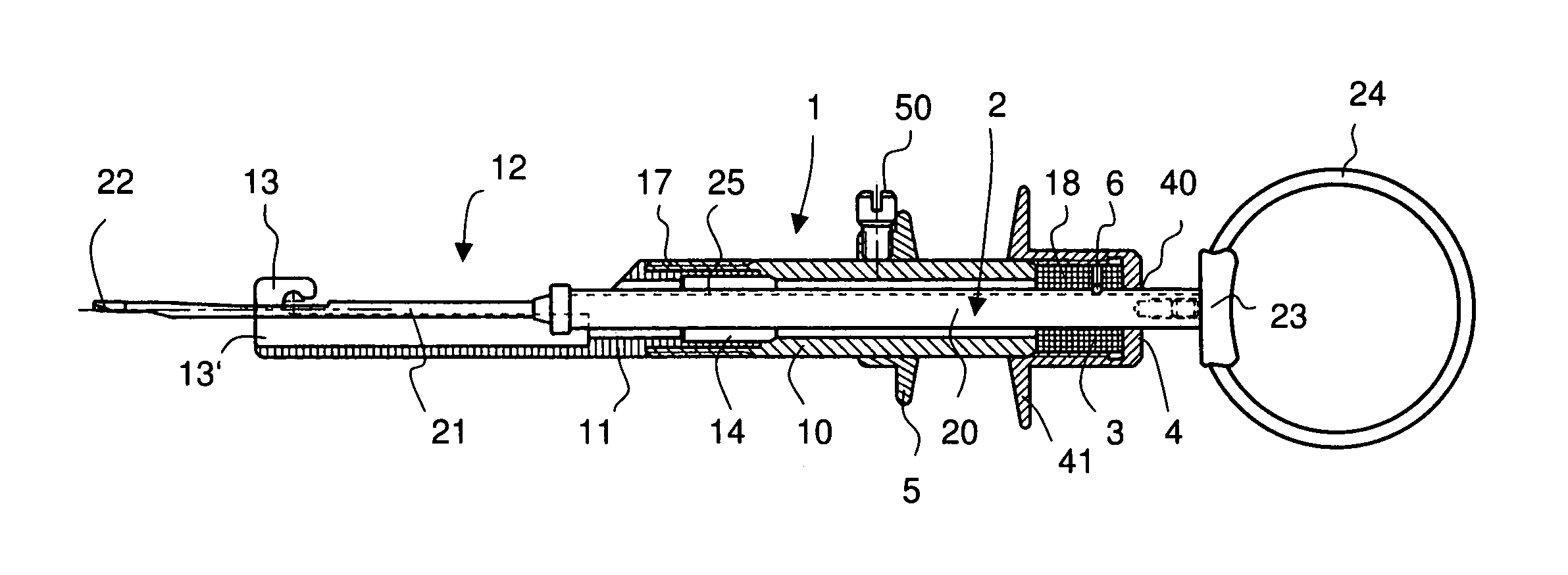
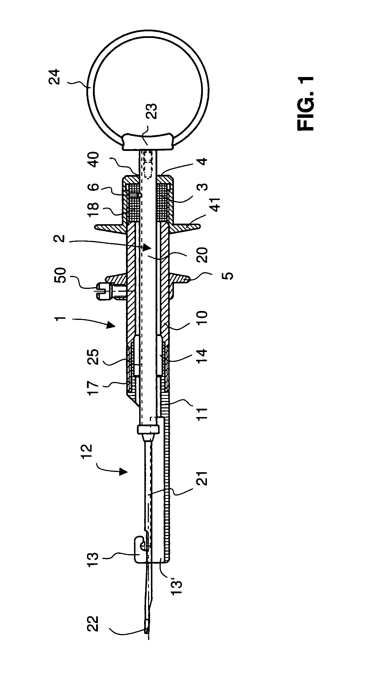
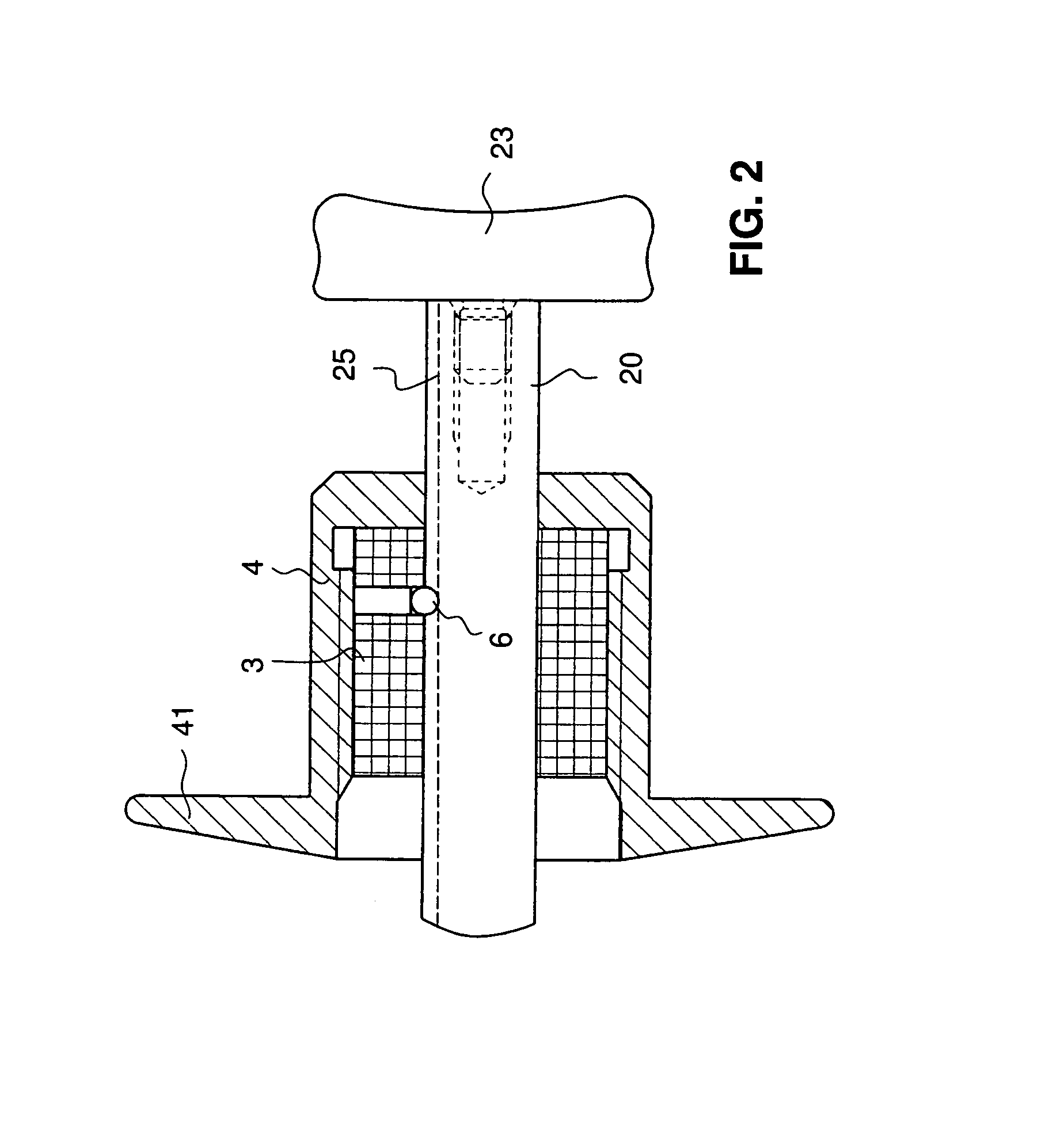
[0016]FIGS. 1 and 2 show an injector according to the invention in a first embodiment. It comprises a grip body 1 in which a plunger 2 is displaceably mounted. Both grip body 1 and plunger 2 are preferably made of metal, in particular titanium.

[0017]The grip body 1 has a sleeve 10 which is closed off at its rear end by a closure cap 4. At its front end, the sleeve 10 merges into a grip front part 11. In the example shown here, the grip front part 11 is a separate component which is screwed to the sleeve 10 via a first thread 17.

[0018]At its forward end directed away from the sleeve 10, the grip front part 11 has a lens holder 13 for holding an artificial lens. Behind the lens holder 13, the grip front part 11 has an elongate, open insert window 12 through which the lens is fitted into the lens holder 13. At its front end, the lens holder 13 has a through-opening 13′ through which the lens is pushed out. As can be seen from FIG. 3, a window 13″ can be formed in the lens holder 13 in ...


PUM


Abstract

A device for inserting a lens into an eye has a grip body (1) with a lens holder (13) for holding the lens, and a plunger (2) which can be displaced in the grip body (1) for guided insertion of the lens into the eye. A ball-bearing bush (3) is arranged in the grip body (1), the plunger (2) being mounted so as to be laterally displaceable in this ball-bearing bush (3). This allows the device to be operated using one hand, said device additionally having good slide properties and permitting an at all times guided lateral or rotational movement of the plunger.

Description

TECHNICAL FIELD[0001]The invention relates to a device for inserting a lens into an eye.PRIOR ART[0002]Nowadays, in ophthalmic surgery, opaque natural eye lenses are replaced by artificial lenses. In this procedure, the patient's opaque lens is first removed. The surgeon then introduces the artificial lens into the eye with the aid of two forceps. The first forceps is used to fold the lens, and the second forceps is used to insert the lens. This demands that the surgeon have a very steady hand and considerable practice in guiding the two forceps.[0003]A device called an injector permits a certain degree of guiding when fitting artificial lenses. This device for inserting a lens into an eye consists mainly of a grip body and of a plunger which can be displaced in the grip body via a thread. In the front area of the grip body there is a lens holder into which a lens to be inserted is placed. By rotating the plunger, this lens can then be pushed through a front opening of the lens hold...

Claims


Application Information

Patent Timeline
Patent Type & Authority Patents(United States)
IPC IPC(8): A61F9/00A61F13/20A61M31/00A61F9/007A61F2/16
CPCA61F2/167
Inventor MEYER, ROLF
Owner ASICO
Why Eureka
Try Eureka