

Scaled suture thread
a suture thread and scale technology, applied in the field of surgical practice, can solve problems such as increasing slippage, and achieve the effect of resisting slippag
- Summary
- Abstract
- Description
- Claims
- Application Information
AI Technical Summary
Benefits of technology
Problems solved by technology
Method used
Image

Examples
Embodiment Construction
[0016] Although the disclosure hereof is detailed and exact to enable those skilled in the art to practice the invention, the physical embodiments herein disclosed merely exemplify the invention, which may be embodied in other specific structures. While the preferred embodiment has been described, the details may be changed without departing from the invention, which is defined by the claims.
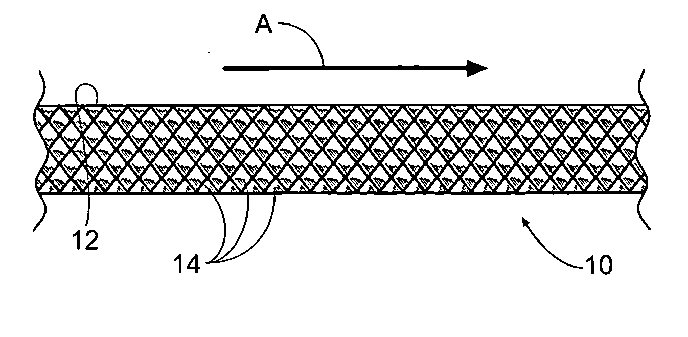
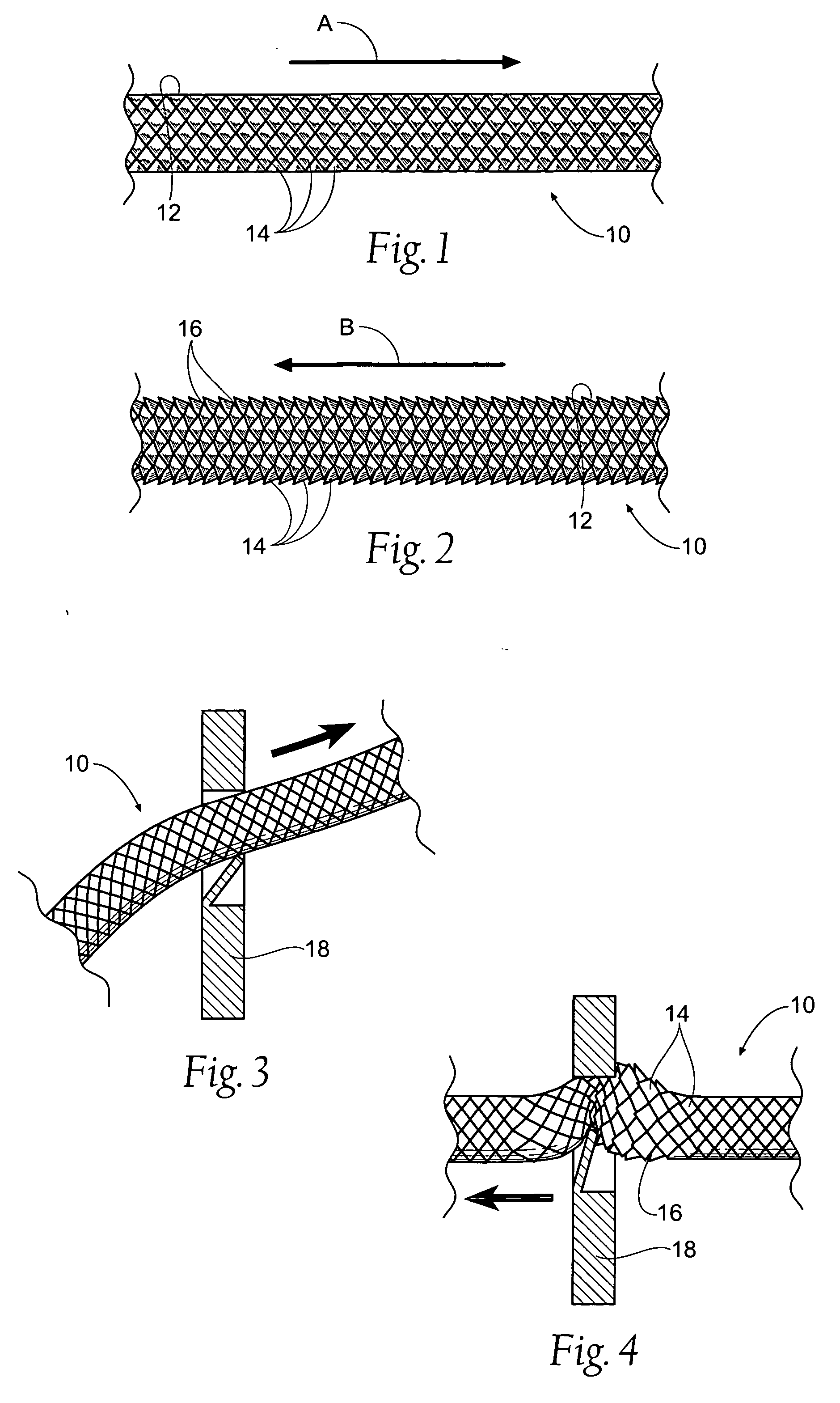
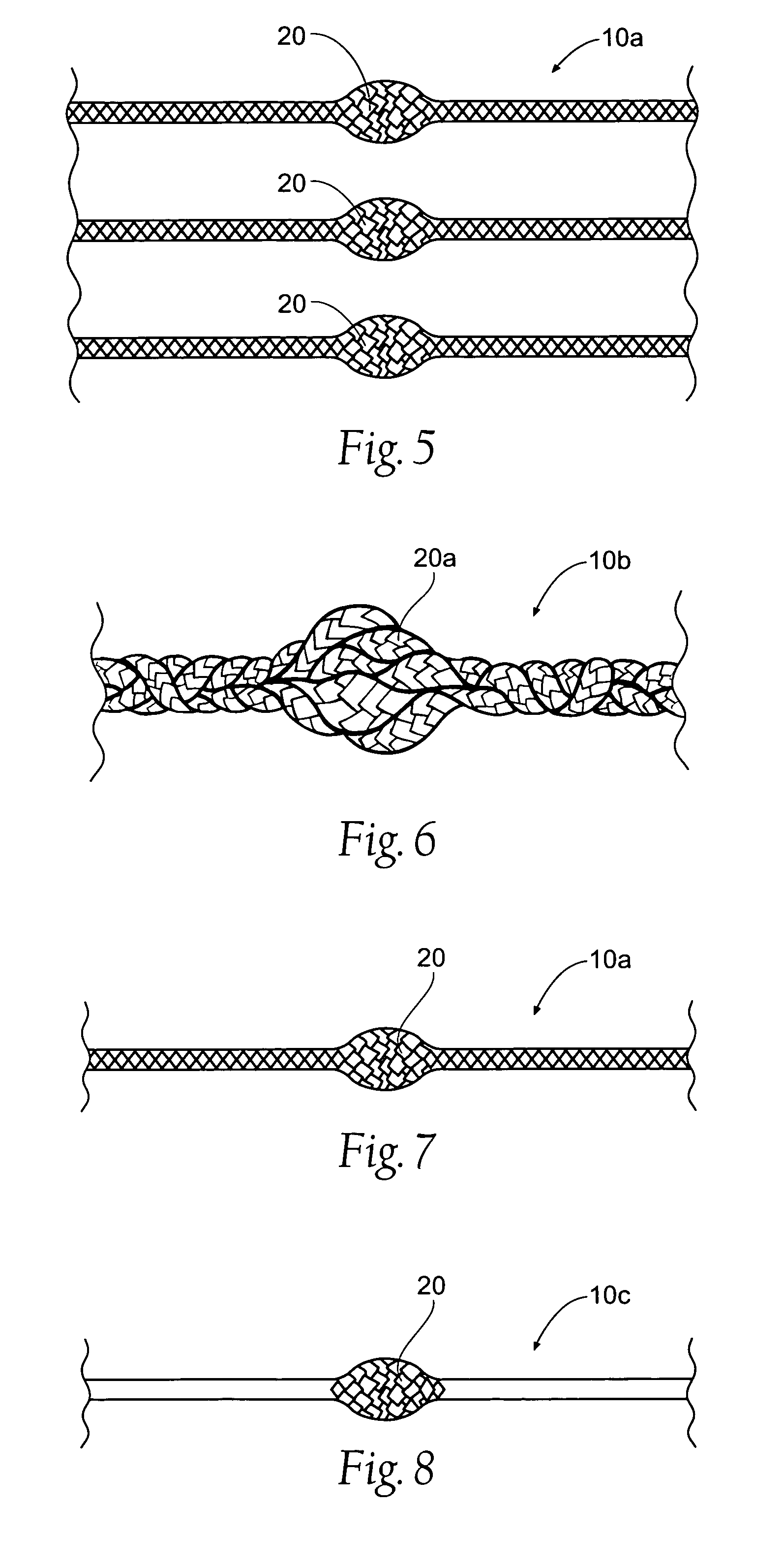
[0017] The present invention is directed to suture thread, and in particular suture thread having unidirectional pull capabilities. Specifically, the present invention pertains to suture thread having the capability to be pulled easily in one longitudinal direction, while resisting movement in an opposite longitudinal direction.
[0018] The purpose of the present invention is to provide a suture thread 10 with an exposed surface 12 having a first coefficient of friction when the thread 10 is moved in a first longitudinal direction and a second coefficient of friction when the thread 10 is moved ...
PUM
| Property | Measurement | Unit |
|---|---|---|
| coefficient of friction | aaaaa | aaaaa |
| thickness | aaaaa | aaaaa |
| lateral movement | aaaaa | aaaaa |
Abstract
Description
Claims
Application Information