Pressure-propelled system for body lumen

a technology of pressure-propelled system and body, which is applied in the field of pressure-propelled system, can solve the problems of endoscope insertion, colon bleed and accidental perforation, and abdominal pain and distention

Active Publication Date: 2005-09-08
G I VIEW LTD (IL)
View PDF99 Cites 88 Cited by
  • Summary
  • Abstract
  • Description
  • Claims
  • Application Information

AI Technical Summary

Benefits of technology

[0066] facilitating passage of fluid out of the lumen from a site within the lumen distal to the piston head.
[0067] In an embodiment, the method includes applying a low friction coating to an outer surface of the piston head intended for contact with the wall of the lumen, the low friction coating being suitable for facilitating sliding of the piston head against the wall of the lumen.

Problems solved by technology

In this manual technique, patients may often complain of abdominal pain and distention because the colon is extended or excessively dilated, thereby necessitating stopping the endoscopic procedure.
Furthermore, it is not unusual for the colon to bleed and be accidentally perforated.
Insertion of an endoscope through the sigmoid colon and into the descending colon, or through the splenic flexure, the transverse colon, the hepatic flexure or parts affected by previous operations may also be accompanied with difficulty.
Because of these reasons, a colonoscopy is typically performed by a relatively small number of skilled practitioners, and the rate of patient pain and discomfort is high.

Method used


Image

  • Pressure-propelled system for body lumen
  • Pressure-propelled system for body lumen
  • Pressure-propelled system for body lumen

Examples


Embodiment Construction

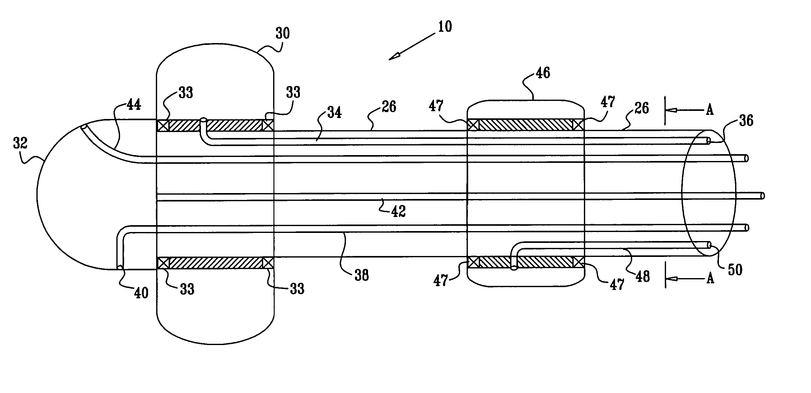
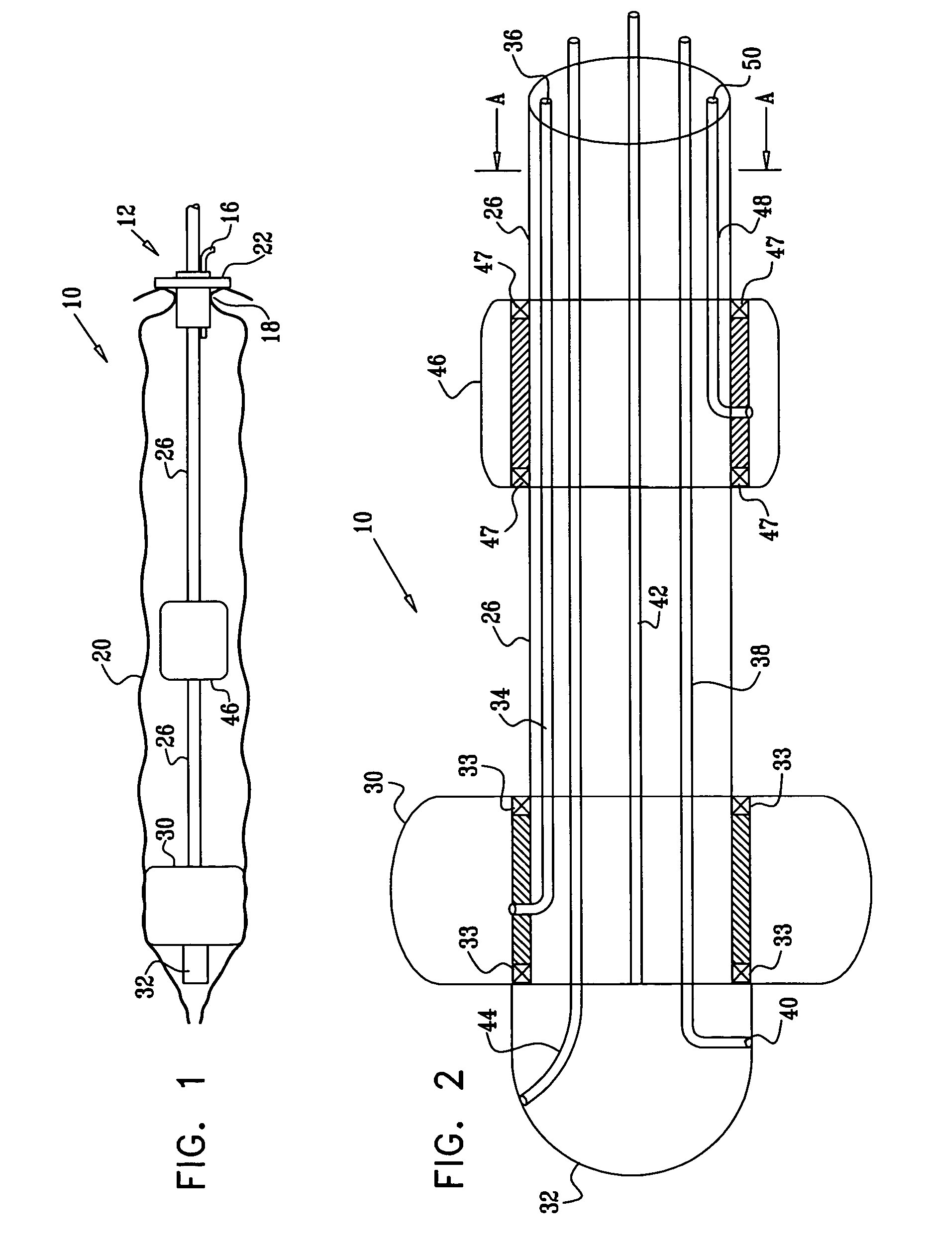
[0395] Reference is now made to FIGS. 1-3, which illustrate a system 10, constructed and operative in accordance with an embodiment of the present invention.

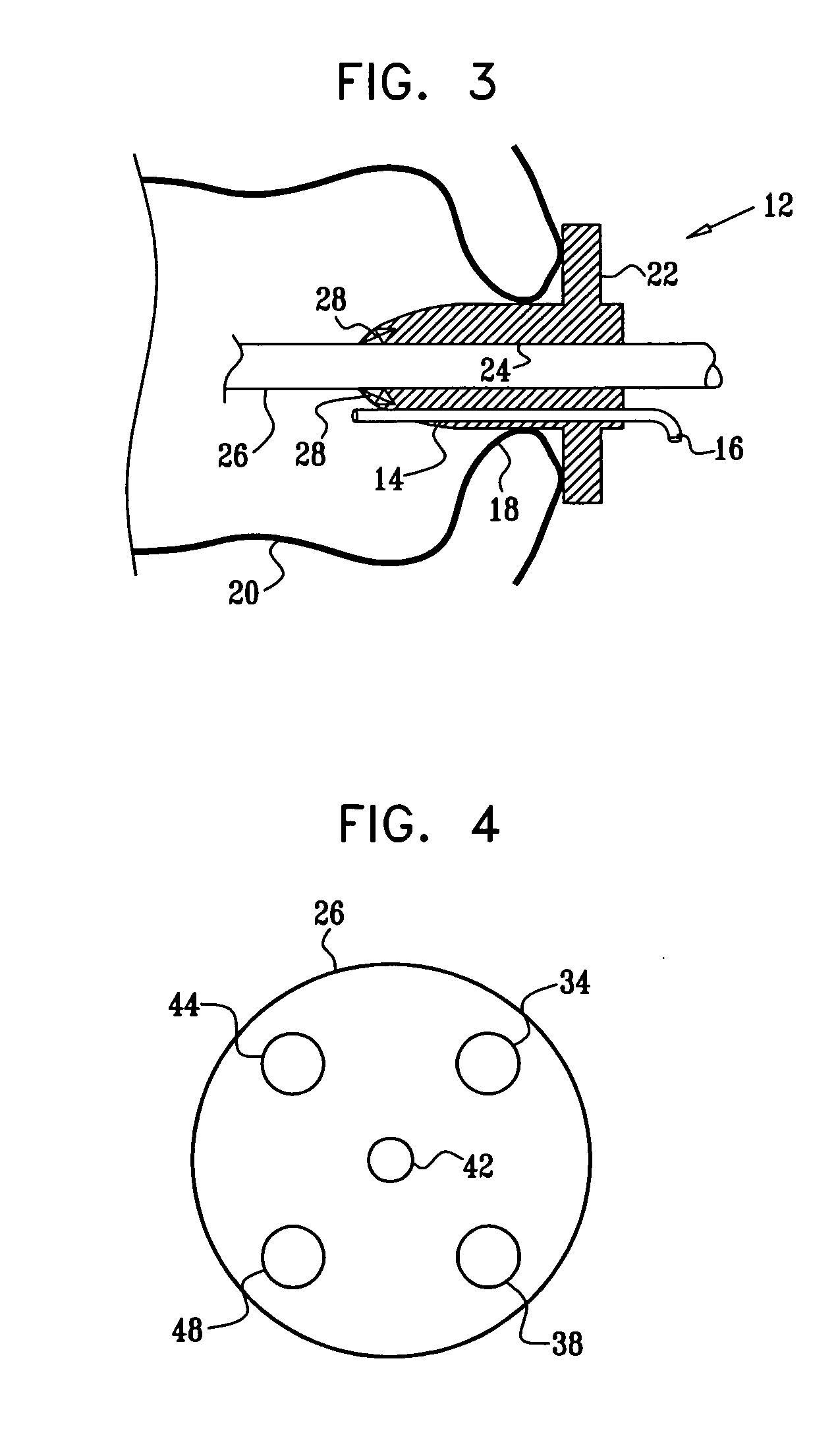
[0396] As seen best in FIG. 3, system 10 may include a guide member 12, which may be constructed of any medically safe material, such as but not limited to, plastic or metal. Guide member 12 may be formed with a first passageway 14 connected to a source 16 of a pressurized biologically-compatible fluid (“fluid pressure source 16”), such as but not limited to, a source of pressurized air, CO2 or water. Guide member 12 may be at least partially insertable into a proximal opening 18 (e.g., the rectum) of a body lumen 20 (e.g., the colon). Guide member 12 may include an annular ring 22 for abutting against the proximal opening 18.

[0397] Guide member 12 may be formed with a bore 24 through which an elongate carrier 26 may be arranged for sliding movement. An O-ring 28 may be provided for dynamically sealing carrier 26 in its slidin...


PUM


Abstract

Apparatus is provided for use with a biologically-compatible-fluid pressure source, the apparatus including an elongate carrier, adapted to be inserted through a proximal opening of a body lumen, and a piston head coupled to a distal portion of the carrier. The piston head is adapted to form a pressure seal with a wall of the lumen after the carrier has been inserted into the lumen, and to be advanced distally through the body lumen in response to pressure from the fluid pressure source. The apparatus is configured to facilitate distal advancement of the piston head by facilitating passage of fluid out of the lumen from a site within the lumen distal to the piston head. The apparatus additionally includes an optical system, coupled to the carrier in a vicinity of the distal portion, the optical system having distal and proximal ends. The optical system includes an image sensor, positioned at the proximal end of the optical system; an optical member having distal and proximal ends, and shaped so as to define a lateral surface, at least a distal portion of which is curved, configured to provide omnidirectional lateral viewing; and a convex mirror, coupled to the distal end of the optical member, wherein the optical member and the mirror have respective rotational shapes about a common rotation axis.

Description

CROSS-REFERENCES TO RELATED APPLICATIONS [0001] The present application is a continuation-in-part of: [0002] (a) U.S. patent application Ser. No. 10 / 838,648 to Gross et al., filed May 3, 2004, entitled, “Pressure-propelled system for body lumen,” and [0003] (b) U.S. patent application Ser. No. 10 / 753,424 to Gross et al., filed Jan. 9, 2004, entitled, “Pressure-propelled system for body lumen.”[0004] The present application claims priority from: [0005] (a) a U.S. provisional patent application ______ to Cabiri et al., filed Sep. 8, 2004, entitled, “Mechanical aspects of pressure-propelled system for body lumen,” and [0006] (b) U.S. Provisional Patent Application 60 / 571,438 to Dotan et al., filed May 14, 2004, entitled, “Omnidirectional and forward-looking imaging device.”[0007] All of the above-mentioned applications are assigned to the assignee of the present application and are incorporated herein by reference.FIELD OF THE INVENTION [0008] The present invention relates generally to...

Claims


Application Information

Patent Timeline
Patent Type & Authority Applications(United States)
IPC IPC(8): A61B1/00A61B1/012A61B1/015A61B1/05
CPCA61B1/00082A61B1/00147A61B1/00156A61B1/31A61B1/015A61B1/05A61B1/012A61B1/00148
Inventor CABIRI, OZGROSS
Owner G I VIEW LTD (IL)
Why Eureka
Try Eureka