
Safe airbag with vertical groove

A technology of airbags and inflatable chambers, applied in vehicle safety arrangement, pedestrian/occupant safety arrangement, vehicle components, etc., can solve the problems of adding components, increasing the risk of component failure, increasing costs, etc.

Inactive Publication Date: 2009-03-25
KEY SAFETY SYST
View PDF14 Cites 4 Cited by
  • Summary
  • Abstract
  • Description
  • Claims
  • Application Information

AI Technical Summary

Problems solved by technology

Complex sensors and controllers increase the number of components, which inherently increases the risk of component failure and causes engineers to use redundant designs that add cost

Method used


Image

  • Safe airbag with vertical groove
  • Safe airbag with vertical groove
  • Safe airbag with vertical groove

Examples


Embodiment Construction

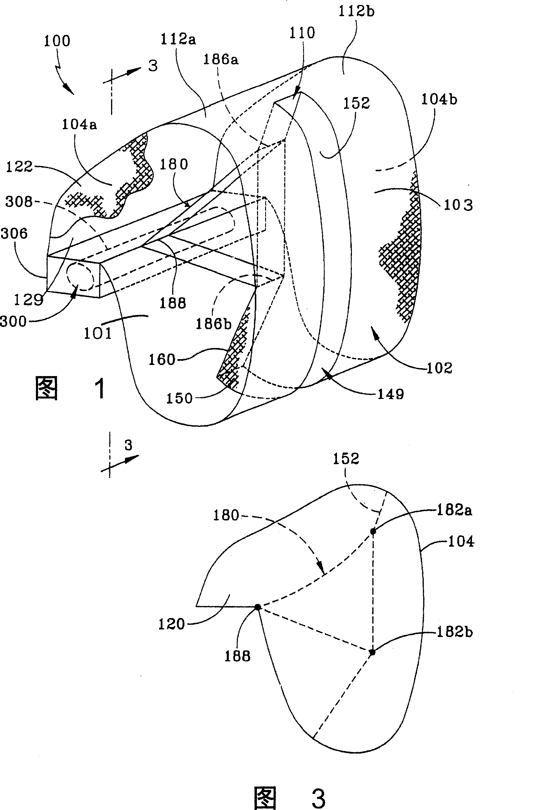
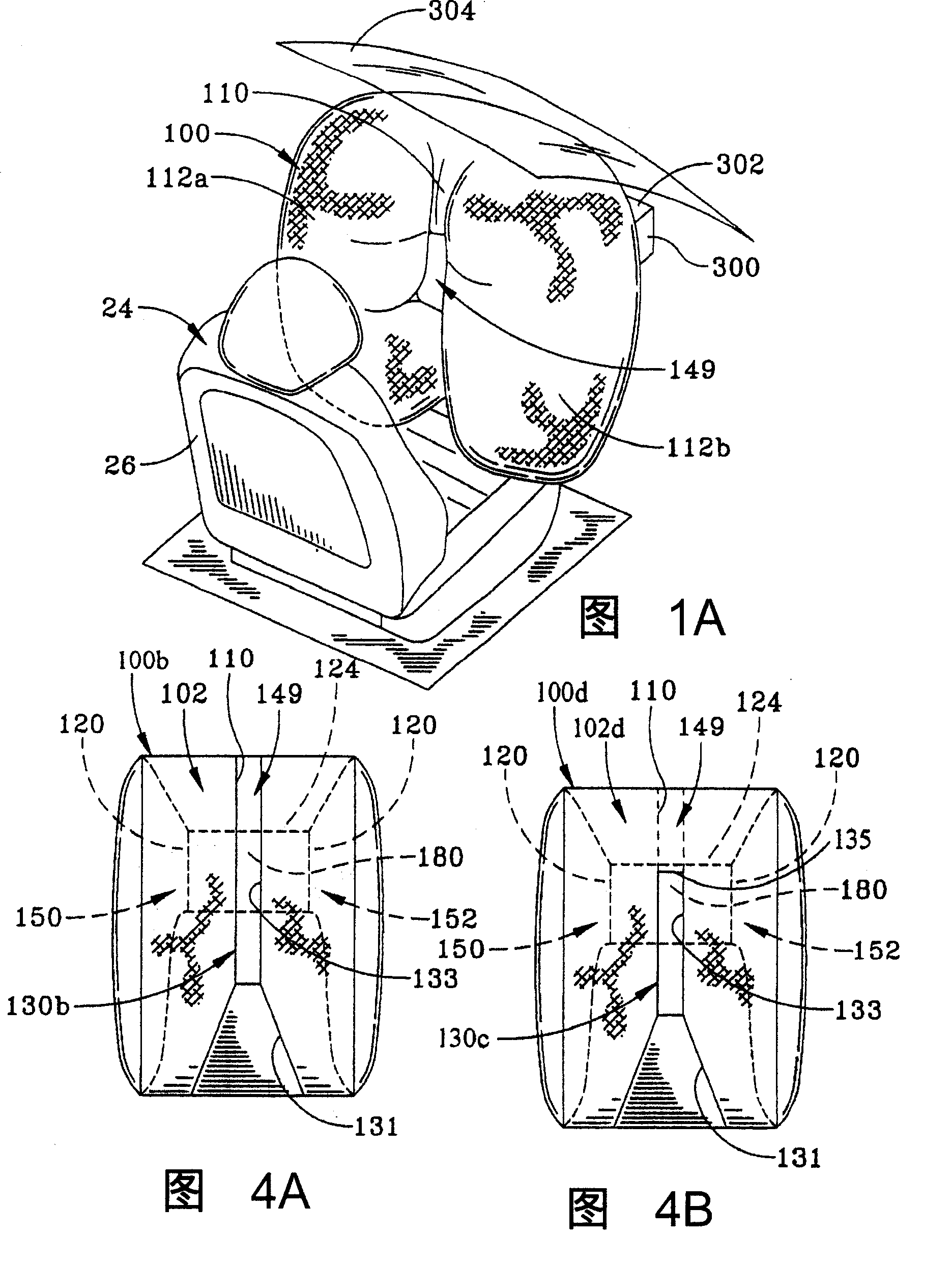
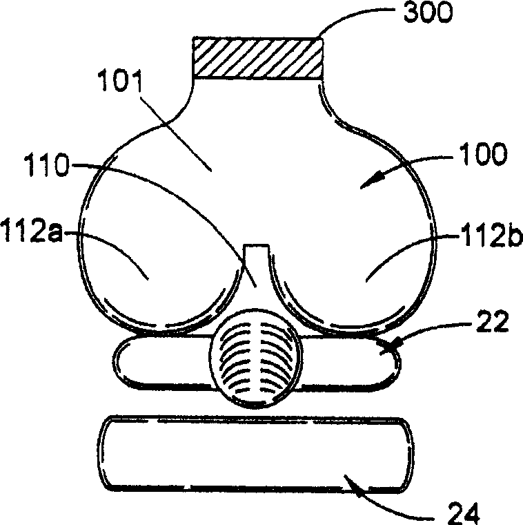
[0034] Figures 1-6 show an airbag having a single inflation chamber configured with a vertically oriented groove portion extending substantially from top to bottom of the portion of the airbag facing the occupant to be protected. The term "recess" as used herein and in the claims means a concavity on a surface, such as a setback or indented surround. In this embodiment, the main panel of the airbag has an elongated slit or opening forming the inlet, opening or mouth of the recess. Figure 1C , 1D , 1E, 8A and 11A show another embodiment utilizing a similar structure to achieve approximately the same size groove portion. The opening on the main piece is reduced in size, and a part of the main piece covers the top of the groove portion when assembled. In a broad sense, the covering portion of the main sheet provides a bridge extending across the top of the groove portion. Figure 4A illustrates the use of trapezoidal groove sections. In Figure 4B, this variation uses a portio...


PUM


Abstract

An airbag (100a) having a single inflatable chamber (101) formed by a main panel (102b) and a pair of side panels (104a, 104b) integrated into or attached along mating edges. The main piece (102b) has an upper portion (135), a front portion (126) and a lower portion. A vertically oriented groove portion (110) is formed on a portion of the airbag (100a) facing forward. A groove portion (110) divides the inflatable chamber (101) into two lug portions (112a, 112b). A tether (180) is located within the inflatable chamber (101) and has one end attached to the groove portion (110) and a second end anchored, thereby constraining the groove portion (110) when the inflatable chamber (101) is inflated. With forward movement, the upper portion (135) of the main piece (102b) extends across the upper region of the groove portion (110). The airbag is used as a frontal airbag, in particular as a frontal airbag on the passenger side.

Description

technical field [0001] The present invention relates to passenger side airbags that deploy from the dashboard of an automobile. Background technique [0002] FIG. 13 shows a prior art conventional passenger side airbag 20 having a separate inflation chamber 330 which is inflated by the airbag inflator 280 . The face portion or panel 320 of the airbag 200 impacts the chest, shoulders and head of the occupant 22 . If the occupant is sitting close to the dashboard of the vehicle and away from the backrest 26 of the seat 24, the velocity at which the airbag impacts the occupant increases. If the occupant's body is in contact with or close to the airbag module cover at the time of airbag deployment, the interaction between the occupant and the airbag is enhanced. [0003] In order to reduce the injury to passengers (including children, infants in child seats, and passengers seated in abnormal sitting postures), some new and more complex airbag systems propose to determine the w...

Claims


Application Information

Patent Timeline
Patent Type & Authority Patents(China)
IPC IPC(8): B60R21/231
Inventor H·庞S·金J·S·库恩
Owner KEY SAFETY SYST
Learn More