Liquid stirring machine

A mixer and liquid technology, which is applied to mixer accessories, mixers with rotating mixing devices, mixers, etc., can solve the problems of large occupied volume and complex structure, reduce manufacturing and assembly costs, simplify components, and package and transport. And the effect of convenient and practical installation and utilization

Inactive Publication Date: 2009-05-27
HUANG MUNG MACHINEY IND
View PDF2 Cites 2 Cited by
  • Summary
  • Abstract
  • Description
  • Claims
  • Application Information

AI Technical Summary

Problems solved by technology

[0006] The main technical problem to be solved by the present invention is to overcome the disadvantages and limitations of the prior art, which are complex in structure, large in size, and must be repeatedly disassembled and assembled, and provide a liquid mixer that uses a rotating disc to exchange two mixing tanks. The barrel is aligned with the stirring device or the extrusion device respectively

Method used


Image

  • Liquid stirring machine
  • Liquid stirring machine
  • Liquid stirring machine

Examples


Embodiment Construction

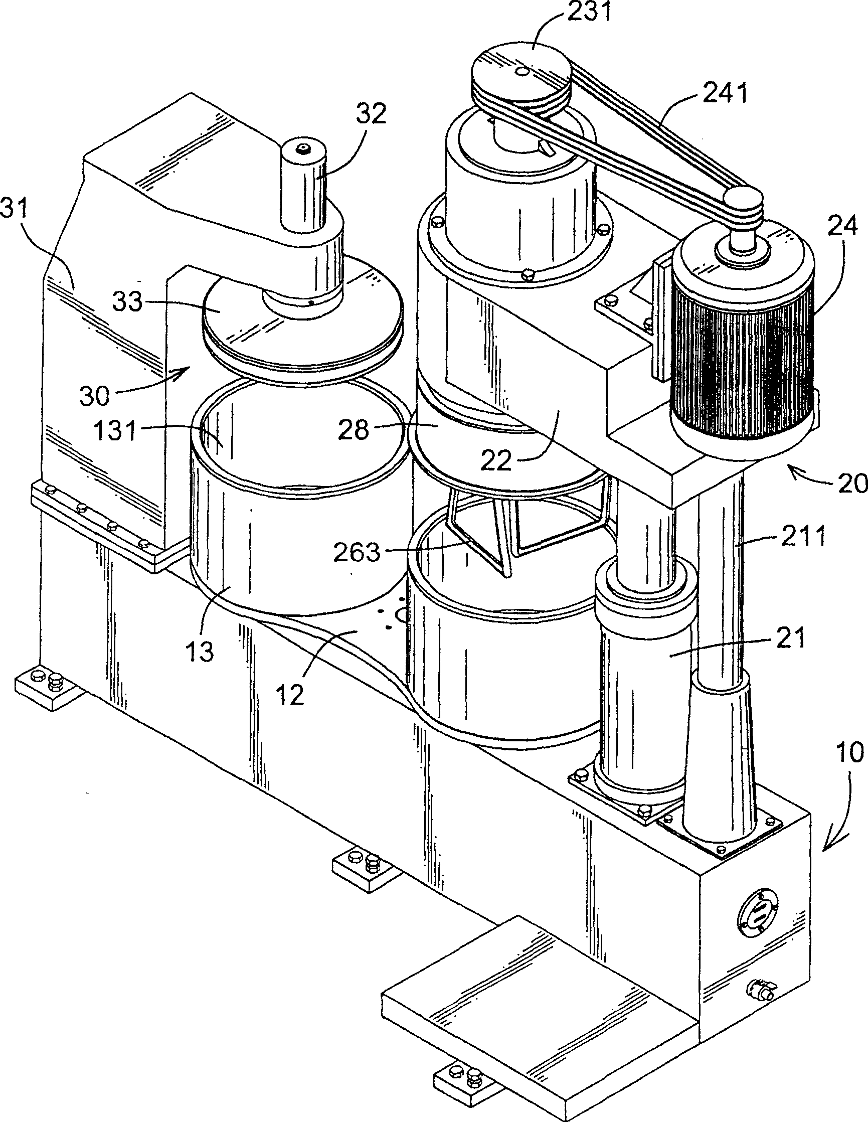
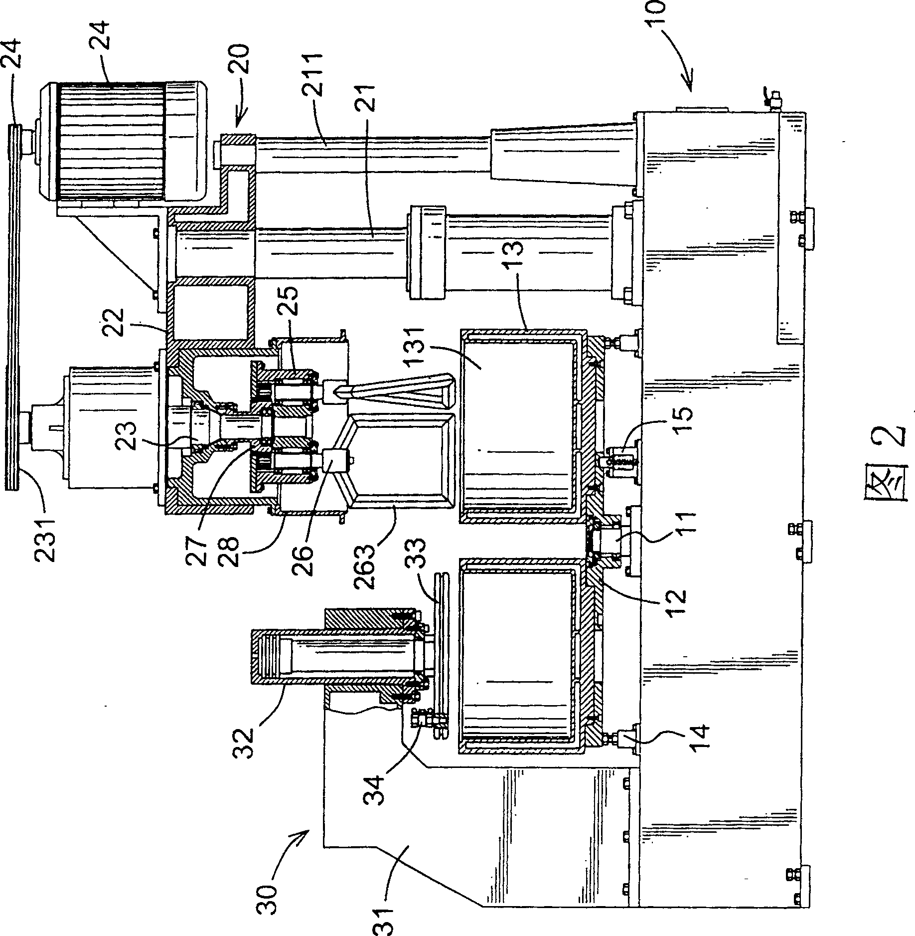
[0055] The present invention is a liquid mixer mainly used for stirring and mixing medium and high viscosity liquids, such as figure 1 , Figure 2 shows a preferred embodiment of the present invention, which is provided with a horizontally elongated base 10, and is respectively provided with a stirring device 20 and an extruding device 30 at the two ends of the base 10 in a facing pattern; in:

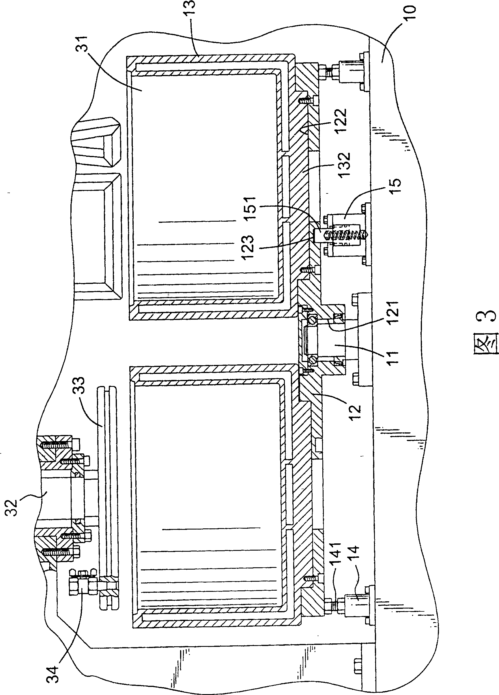
[0056] As shown in Figures 2 and 3, the base 10 is a horizontally elongated seat structure with a hollow assembly space inside for installation of hydraulic oil tanks and other related components. A shaft seat 11 is protruding from the center of the top of the base 10. Let a long rotating disk 12 be rotatably coupled to the top of the shaft seat 11. As shown in the figure, the rotating disk 12 is provided with arc edges on both ends and concave arc edges on both sides of the central part. The elongated plate, and at the bottom of the central position of the rotating disk 12 is provide...


PUM


Abstract

A liquid mixer is provided, which is provided with a cross long base, a mixing device and a extruding device are arranged connectedly at the two sides of the two ends of the base correspondingly; an axle base is arranged at the middle of the top on the base, the axle base is connected with a rotating plate in rotating shape, the rotating plate is connected with a mixing barrel at the two end sides at the top of the rotating plate, the two mixing barrels are opposite to the work position of the mixing device and the extruding device. The invention not only can simplify the structure of the mixer and reduces the occupying space and volume, but also can use the way of rotating the rotating plate directly, doesn't need to assemble and disassemble the mixing barrel, can changing the work position of the two mixing barrels simply and quickly, and improves the operating and using convenience of the mixer greatly.

Description

technical field [0001] The invention relates to a liquid mixer. Background technique [0002] see Image 6 Shown is a kind of agitator that is currently used for stirring and mixing medium and high viscosity liquids. The agitator is provided with a base 90, and a stirring device 91 and an extruding device 92 are respectively arranged on the two halves of the base 90, and on the base 90 A slide rail 93 is provided between the working position of the top relative to the stirring device 91 and the extrusion device 92, for the sliding and transposition of the two mixing barrels 94; [0003] The aforesaid agitating device 91 is provided with a pair of spaced apart lifting and lowering cylinders 911 that are combined with the base 90, and a stirring upper seat 912 is provided between the tops of the two lifting and lowering cylinders 911, and a motor and gears are combined on the stirring upper seat 912. group, protective cover 913 and a plurality of agitators 914 and other relat...

Claims


Application Information

Patent Timeline
Patent Type & Authority Patents(China)
IPC IPC(8): B01F7/16B01F3/10B01F15/02B01F23/47
Inventor 陈汉忠
Owner HUANG MUNG MACHINEY IND
Why Eureka
Try Eureka