

High gain isolating active clamping boost transducer
An isolated, high-gain technology, applied in the direction of converting DC power input to DC power output, instruments, and adjusting electrical variables, can solve the problems of large current stress of power switch tubes, insufficient output voltage gain, and large switching losses. Achieve the effect of increasing output gain, improving circuit efficiency, and reducing additional components
- Summary
- Abstract
- Description
- Claims
- Application Information
AI Technical Summary
Problems solved by technology
Method used
Image

Examples
Embodiment Construction
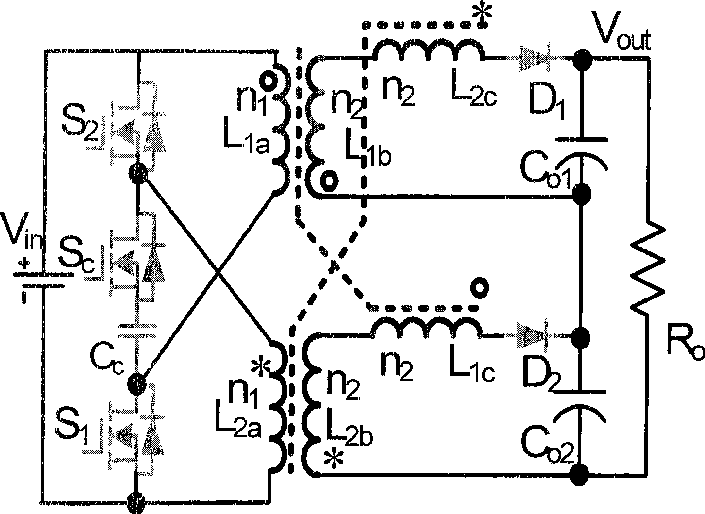
[0008] see figure 1 , the high-gain isolated active clamp boost converter of the present invention comprises two power switch tubes S1, S2, two freewheeling diodes D1, D2, two output capacitors Co1, Co2 and two coupling inductors, The first coupled inductor has three windings L1a, L1b, L1c, the second coupled inductor has three windings L2a, L2b, L2c, the drain of the first power switch tube S1 is connected to one end of the first winding L1a of the first coupled inductor, and the second coupled inductor has three windings L2a, L2b, L2c. The source of a power switch tube S1 is connected to one end of the first winding L2a of the second coupled inductor, the source of the second power switch tube S2 is connected to the other end of the first winding L2a of the second coupled inductor, and the second power switch The drain of the tube S2 is connected to the other end of the first winding L1a of the first coupling inductance, one end of the second winding L1b of the first couplin...
PUM
 Abstract
Description
Claims
Application Information