A Ship Cathodic Protection Isolated Switching Power Converter from Shore Power

A switching power supply and cathodic protection technology, applied in the direction of regulating electrical variables, high-efficiency power electronic conversion, conversion of DC power input to DC power output, etc. problem, to achieve the effect of improving output power level, reducing loss and high conversion efficiency

Active Publication Date: 2020-12-25
SHANGHAI MUNICIPAL ELECTRIC POWER CO
View PDF7 Cites 0 Cited by
  • Summary
  • Abstract
  • Description
  • Claims
  • Application Information

AI Technical Summary

Problems solved by technology

Aiming at the shortcomings of current flyback converters, such as severe switching loss, high voltage and current stress of the switch tube, low conversion efficiency, and serious switch tube loss, it provides a reasonable control method, low switch tube current stress, and can realize zero switch tube. Cathodic protection isolated switching power supply with current conduction and stable output current

Method used


Image

  • A Ship Cathodic Protection Isolated Switching Power Converter from Shore Power

Examples


Embodiment 1

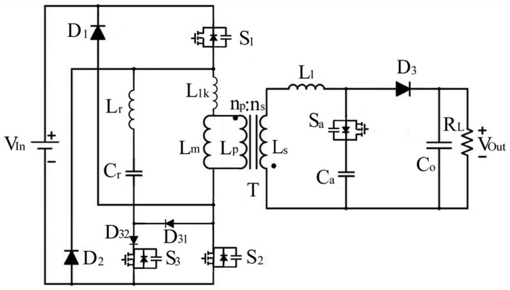
[0072] according to figure 1 As shown in the electrical principle topology diagram, a cathodic protection isolated switching power supply converter with an output power of 60W and an output voltage of 24V is designed. The switching power converter parameter is the input voltage V In =250V, output power V Out =60W, output voltage 24V, excitation inductance L m It is 600μH, the resonant inductance is 15μH, the DC blocking capacitor is 3.5μF, the switching frequency is 80kHz, and the output filter capacitor is 480μF.

[0073] The driving voltage V of the switching tube is detected by an oscilloscope and other instruments. gs , Switch drain-source voltage V ds , Resonant inductor current i Lr and the secondary rectifier tube current i Dr and voltage V Dr the experimental waveform. The voltage stress of all switch tubes is clamped at the input voltage, and the zvs conduction of all switch tubes is realized. Resonant inductor current i Lr The reverse peak value is much sma...

Embodiment 2

[0076] according to figure 1 As shown in the electrical principle topology diagram, a cathodic protection isolated switching power supply converter with an output power of 48W and an output voltage of 12V is designed. The switching power converter parameter is the input voltage V In =130V, output power V Out =48W, output voltage 12V, excitation inductance L m It is 600μH, the resonant inductance is 15μH, the DC blocking capacitor is 3.5μF, the switching frequency is 65kHz, and the output filter capacitor is 480μF.

[0077] The driving voltage V of the switching tube is detected by an oscilloscope and other instruments. gs , Switch drain-source voltage V ds , Resonant inductor current i Lr and the secondary rectifier tube current i Dr and voltage V Dr the experimental waveform. The voltage stress of all switch tubes is clamped at the input voltage, and the zvs conduction of all switch tubes is realized. Resonant inductor current i Lr The reverse peak value is much sma...


PUM


Abstract

The utility model relates to a ship cathodic protection isolation switch power converter obtained from shore power, which belongs to the field of power distribution. It includes at least one flyback transformer, two main control switch tubes and two auxiliary switch tubes; it uses the secondary winding of the flyback transformer and the switch capacitor connected in series to improve the output power level of the converter; uses the primary side The series circuit composed of the auxiliary switch tube and the clamp capacitor and the series circuit composed of the auxiliary switch tube and the clamp capacitor on the secondary side can absorb and transfer most of the leakage inductance energy of the flyback transformer losslessly, and realize the two main control switch tubes zero-current turn-on; use the parasitic parallel capacitance of the two main control switch tubes to realize zero-voltage turn-off of the first and second main control switch tubes, and use the first and second main control switch tubes and the primary and secondary Reasonable matching of the auxiliary switch tubes realizes zero-voltage turn-on and zero-voltage turn-off of the two auxiliary switch tubes. It reduces the voltage and current stress of the switch tube, has high conversion efficiency, and can increase the output of the converter.

Description

technical field [0001] The invention belongs to the field of power distribution, in particular to a marine cathodic protection isolated switching power supply converter. Background technique [0002] Ships docked at the dock need shore power to supply energy. If the hull does not take effective anti-corrosion measures, it will lead to extremely serious galvanic corrosion. [0003] Cathodic protection is an effective measure widely used in metal anticorrosion in seawater environment. The advantage of impressed current cathodic protection system is that it adopts automatic control, and the size of the output current can be automatically adjusted so that the surface of the protected structure is within the protection potential range. The impressed current cathodic protection system has high reliability; the output current of the cathodic protection system can be adaptively changed according to the working conditions, so that the ship's metal materials are in a better protection...

Claims


Application Information

Patent Timeline
Patent Type & Authority Patents(China)
IPC IPC(8): H02M3/335
CPCH02M3/33569H02M1/0058Y02B70/10
Inventor 陈俊逸唐海峰陈祺陈婧
Owner SHANGHAI MUNICIPAL ELECTRIC POWER CO
Why Eureka
Try Eureka