Magnetic energy-saving lamp

An energy-saving lamp and magnetic technology, applied in lighting devices, independent lighting devices, discharge lamps, etc., can solve problems such as luminous flux reduction and loss of luminous flux

Inactive Publication Date: 2009-07-08
常涛涛
View PDF2 Cites 0 Cited by
  • Summary
  • Abstract
  • Description
  • Claims
  • Application Information

AI Technical Summary

Problems solved by technology

There is a problem involved here: setting a magnetic field source near the tube body of the lamp may lose part of the luminous flux, reducing the luminous flux that can be measured and utilized by people

Method used


Image

  • Magnetic energy-saving lamp
  • Magnetic energy-saving lamp
  • Magnetic energy-saving lamp

Examples


Embodiment Construction

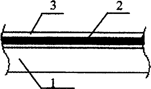
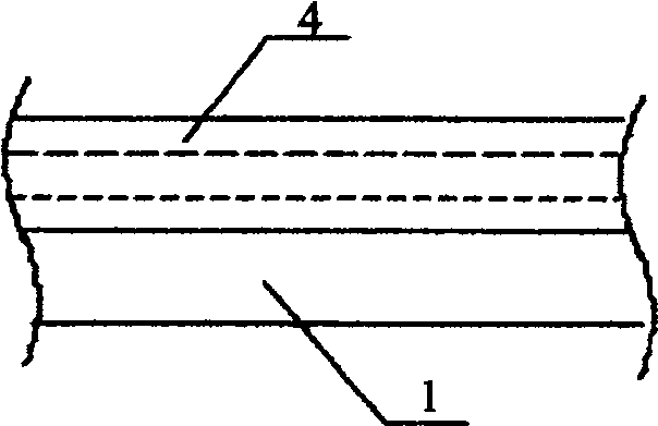
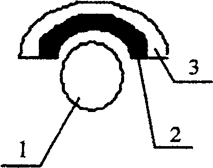
[0055] figure 1 It is a partial structure diagram of the principle of the magnetic energy-saving lamp of the present invention. A magnetic field source capable of generating a magnetic field to change the state of the lamp tube is installed in the vicinity of the lamp tube 1 installed on the bracket including the control circuit, and its polar plane is along the direction of the lamp tube. axial distribution. The magnetic field source is composed of a permanent magnet 4. The permanent magnet 4 has an N pole 2 and an S pole 3. The N pole 2 is facing the wall of the lamp tube. The magnetic field source in the vicinity of the lamp tube 1 can generate and pass through the inside of the lamp tube 1. And the magnetic field lines of deflection force are applied to the electron flow flowing through the tube body of the lamp tube 1 when emitting light. Regardless of whether the above-mentioned magnetic field source is attached to the lamp tube 1 or the support of the lamp tube 1 or an...


PUM


Abstract

The present invention is a design method and device for a magnetic energy-saving lamp, which at least includes a lamp tube and a support frame, and may also include control circuits such as known ballasts and starters. A magnetic field force is applied inside the tube. The said applying magnetic field force into the lamp tube is to strengthen the light emitting process of the lamp tube and improve the light effect; the said magnetic field source can be arranged on the supporting frame. The magnetic field source can be arranged on the surface of the lamp tube. Said magnetic field source can be arranged inside the lamp tube. The design method and device of the magnetic energy-saving lamp can significantly improve the total light efficiency and total power factor of the lamp compared with existing lighting devices, significantly prolong the service life, and have simple structure, convenient use and high reliability.

Description

Technical field [0001] The invention relates to a design method and device for a magnetic energy-saving lamp, in particular to a design method and device for a magnetic energy-saving lamp, in particular to a kind of lighting device whose total light efficiency and total power factor are significantly improved and service life is significantly extended, and it can be widely used in the field of fluorescent lamp lighting with the highest degree of versatility. The applied design method and device of a magnetic energy-saving lamp with simple structure, convenient use and high reliability. Background technique [0002] In the lighting field, gas discharge lamps (including fluorescent lamps and neon lamps, etc.), especially fluorescent lamps, are widely used because of their advantages of high luminous efficiency and long life. Gas discharge lamp lighting devices have some common features, and the following description takes fluorescent lamp lighting devices as an example. [00...

Claims


Application Information

Patent Timeline
Patent Type & Authority Patents(China)
IPC IPC(8): H01J61/00H01J65/00H01J9/00F21S6/00
Inventor 常涛涛赵德宏
Owner 常涛涛
Why Eureka
Try Eureka