Inductive device

A technology of induction device and assembly part, applied in the direction of electrical components, electric switches, circuits, etc., can solve problems such as affecting the use quality, dust adhesion, affecting the conduction effect of ball switches, etc.

Active Publication Date: 2009-07-15
ONCQUE CORP
View PDF3 Cites 0 Cited by
  • Summary
  • Abstract
  • Description
  • Claims
  • Application Information

AI Technical Summary

Problems solved by technology

[0004] Although the ball switch 100 can achieve conduction through the ball 102 contacting the taper portion 1031, since the terminal 103 is in a suspended state when inserted into the housing 101, the precision of the jig operation must be very high. In order to make the taper 1031 flush to produce switching action, as long as there is a slight difference in position, it will lose its function. In addition, the terminal 103 is only positioned by inserting into the through hole 1041, which is not stable and is easily caused by external force factors. Shaking will affect the sensing sensitivity of the ball switch 100
[0005] In addition to the ball switch 100 can be used as figure 2 The shown vertical installation on a circuit board 105 is used for the use mode of the normally open state, and it can also be used as image 3 As shown, first bend the terminal 103 and then install it on the circuit substrate 105, so that there is an angle θ between the casing 101 and the circuit substrate 105 for the use mode of the normally closed state. Since the casing 101 is suspended in the air, it is easy to cause External factors change the included angle θ, causing the ball switch 100 to lose its function and relatively affect the quality of use
[0006] In addition, the ball 102 of the ball switch 100 will contact the housing 101 during the rolling process. When the housing 101 is not cleaned during packaging and dust remains, the dust will stick to the surface of the ball 102, resulting in the The conductivity between the ball 102 and the terminal 103 becomes poor, which in turn affects the conduction effect of the ball switch

Method used


Image

  • Inductive device
  • Inductive device
  • Inductive device

Examples


Embodiment Construction

[0029] The sensing device according to the present invention will be described in detail below with reference to the accompanying drawings and preferred embodiments.

[0030] Before the present invention is described in detail, it should be noted that the relative position terms used in the following descriptions, such as "horizontal direction X" and "vertical direction Y", are based on the directions shown in each figure, and are similar to Components are denoted by the same number.

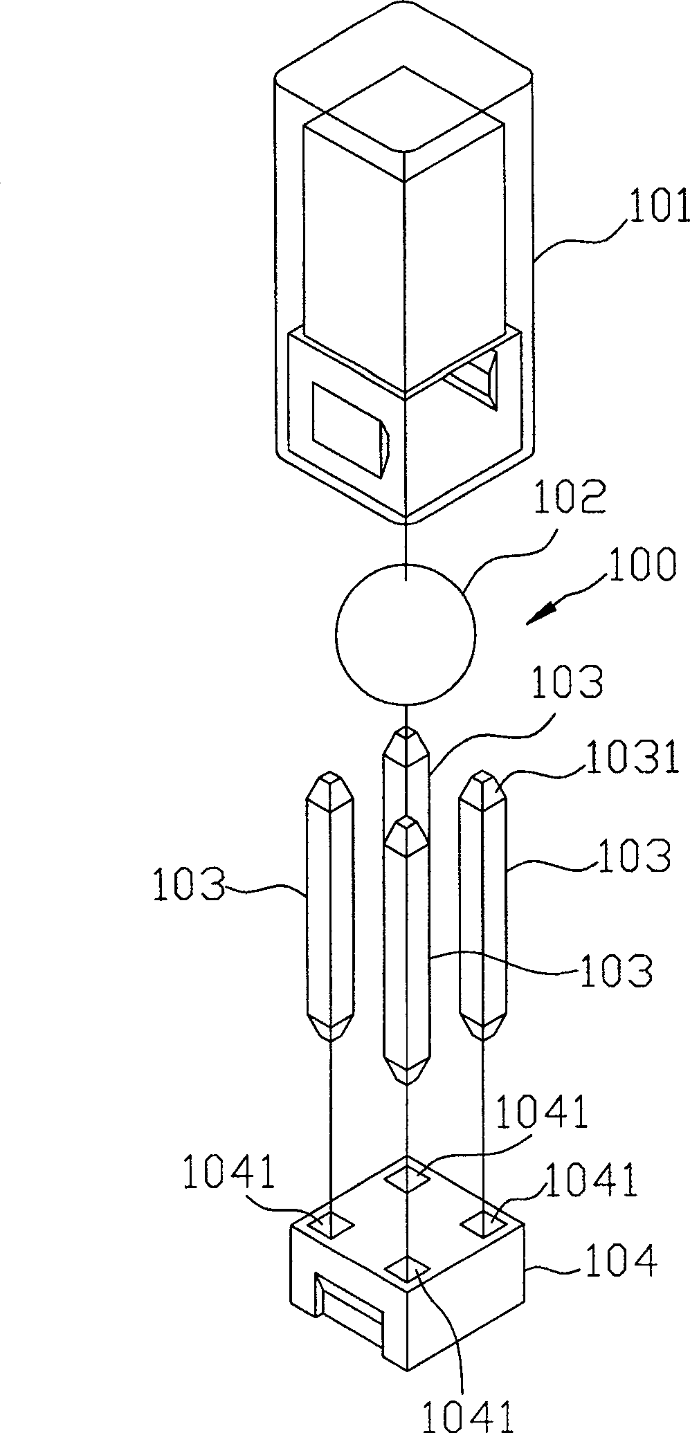
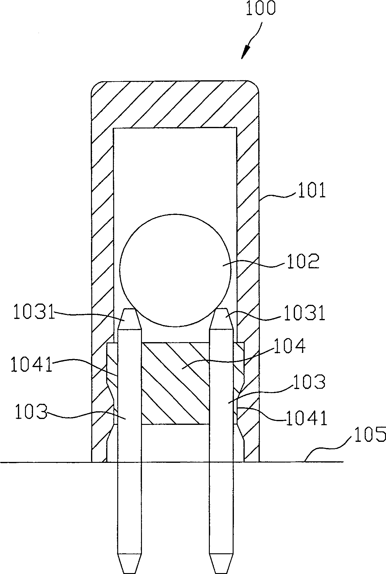
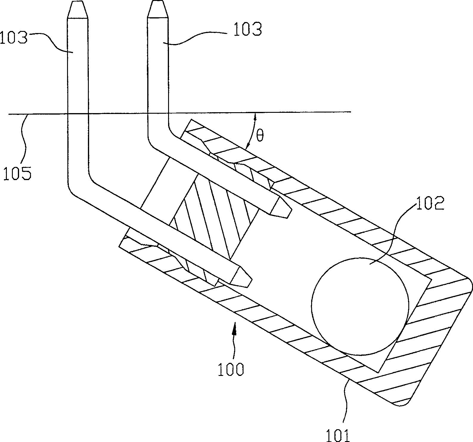
[0031] refer to Figure 4 , Figure 5 , Image 6 , A first preferred embodiment of the sensing device of the present invention includes a hollow seat body 1 , two terminal units 200 , and a ball 4 .

[0032] The hollow seat body 1 is made of insulating material, including a first side 11 and a second side 12 in opposite directions, a receiving hole 13 communicating with the first side 11 and the second side 12, and a plurality of The assembly portion 14 respectively extends outward from the ...


PUM


Abstract

The sensing device includes following parts: a hollow seat; two terminal units with opposite first side face and second side face installed and positioned inside the hollow seat; current conducting ball located in a accommodation hole in the seat and position-limited by the terminal units. Each terminal unit includes separated a first terminal and a second terminal. Each first terminal and second terminal possesses a main body portion, a terminal portion extended from the main body portion along upright direction, and an extension portion extended from inner side face of the main body portion along horizontal direction. When the sensing device is installed on a circuit base plate vertically, the ball contacts second terminals only so that the sensing device is in off state. When the sensing device is tilted, the ball contacts first terminals and second terminals as well so that the sensing device is in on state. The invention possesses good sensing effect.

Description

technical field [0001] The invention relates to a switch, in particular to an induction device for electronic products. Background technique [0002] refer to figure 1 , figure 2 , an existing ball switch 100 has a housing 101, a ball 102, four terminals 103 and a block 104. [0003] When assembling, put the ball 102 into the housing 101, and block the opening of the housing 101 with the block 104 to block the ball 102, and then use a jig (not shown) to insert the terminal 103 into the housing 101. The four through holes 1041 of the block 104 to each taper portion 1031 extend into the housing 101 to complete the assembly. [0004] Although the ball switch 100 can achieve conduction through the ball 102 contacting the taper portion 1031, since the terminal 103 is in a suspended state when inserted into the housing 101, the precision of the jig operation must be very high. In order to make the taper 1031 flush to produce switching action, as long as there is a slight diff...

Claims


Application Information

Patent Timeline
Patent Type & Authority Patents(China)
IPC IPC(8): H01H35/02H01H3/50
Inventor 周添铭
Owner ONCQUE CORP
Why Eureka
Try Eureka