Parallel crank guide rod self-rotating positioning mechanical arm

A technology of manipulators and guide rods, applied in the field of manipulators, can solve problems such as low positioning accuracy, complicated mechanism, and limited positioning methods, and achieve the effects of simple structure, reliable clamping, and low positioning dependence

Inactive Publication Date: 2010-02-10
HARBIN ENG UNIV
View PDF9 Cites 0 Cited by
  • Summary
  • Abstract
  • Description
  • Claims
  • Application Information

AI Technical Summary

Problems solved by technology

[0003] Pliers-type manipulators are not stable enough when gripping overlapping objects, and to increase stability, additional structures are necessary to complicate the mechanism
The screw nut type manipulator itself requires very high design precision, and the manipulator moves slowly when picking up objects, and the efficiency is low.
Moreover, the positioning accuracy of traditional manipulators is low, the positioning methods are limited, and the grasping of light-weight and large target objects is not stable enough
In particular, it cannot be positioned by the manipulator itself, and the positioning accuracy of the robot body is high, which increases the difficulty of controlling the robot body

Method used


Image

  • Parallel crank guide rod self-rotating positioning mechanical arm
  • Parallel crank guide rod self-rotating positioning mechanical arm
  • Parallel crank guide rod self-rotating positioning mechanical arm

Examples


Embodiment Construction

[0019] The present invention is described in more detail below in conjunction with accompanying drawing example:

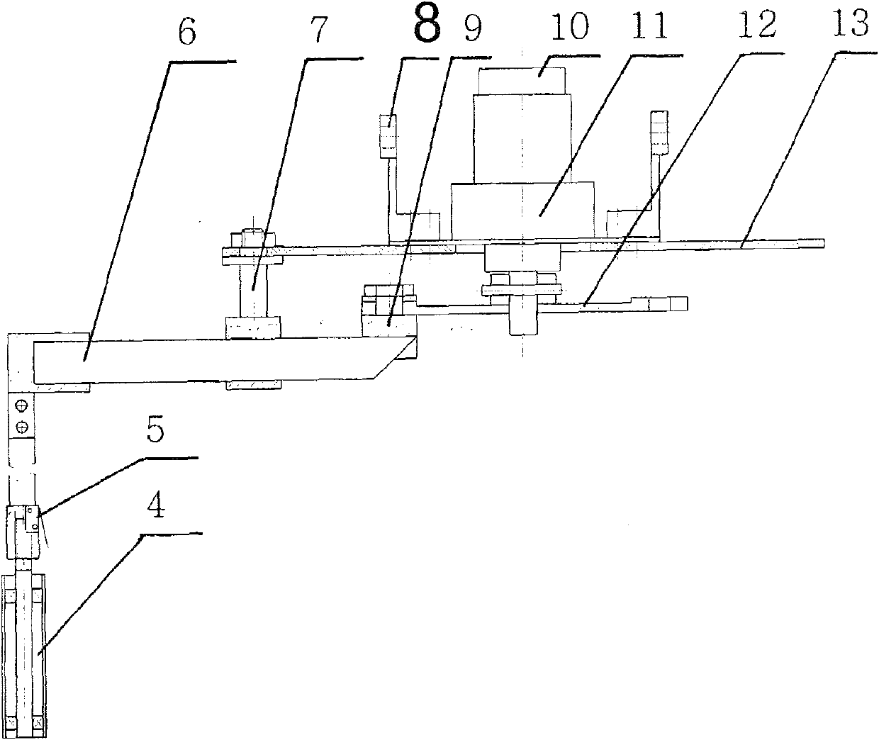
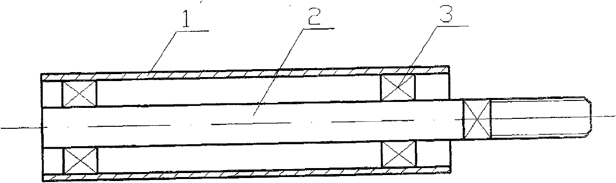
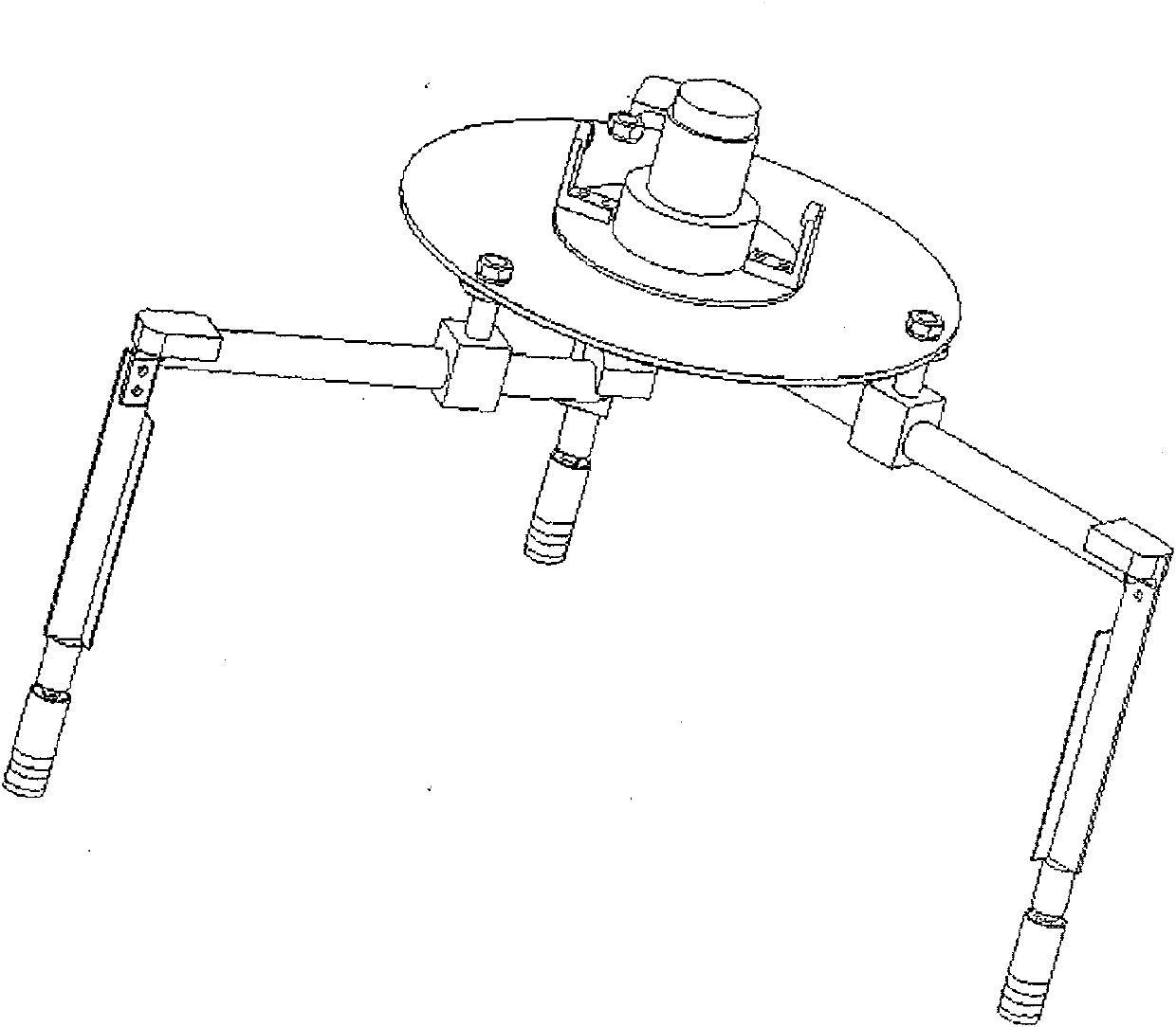
[0020] combine figure 1 , the parallel crank guide bar rotation positioning manipulator is composed of four parts: the interface frame, the drive positioning, the parallel crank guide bar clamping mechanism and the rotation positioning finger; the interface frame includes a fixed plate 13 and a manipulator interface mechanism 8 installed on the fixed plate The drive positioning part includes a motor 11 installed on the fixed disk, a motor code disc 10 installed at the rear of the motor, and a travel switch 5 installed on the end of the guide rod 6; the parallel guide rod clamping mechanism includes a guide rod 6, rotation movement Auxiliary 7, crank rotating pair 9 and the crank disc 12 that are connected on the motor output shaft, guide rod 6 is hinged with crank disc 12 by crank rotating pair 9, and rotation moving pair 7 is arranged between fixed disc 13 and gu...


PUM


Abstract

The invention provides an autorotation location manipulator of a parallel crank guide, which comprises an interface frame, driving location, a parallel crank guide clamping mechanism and autorotationlocation fingers, wherein, the interface frame comprises a fixed disc 13 and a manipulator interface mechanism 8 arranged on the fixed disc; the driving location part comprises a motor 11 arranged onthe fixed disc, a motor code disc 10 arranged at the back of the motor and a travel switch 5 at the terminal end of the guide 6; the parallel crank guide clamping mechanism comprises a guide 6, an autorotation revolute joint 7, a crank revolute joint 9 and a crank disc 12 connected with the motor output shaft. The guide 6 is articulated with the crank disc 12 by the crank revolute joint 9 and theautorotation revolute joint 7 is arranged between the fixed disc 13 and the guide 6. The autorotation location manipulator has the advantages of autorotation location and low dependence on the noumenon location of robots. The clamping gesture of objects in the manipulator is adjusted by autorotation location fingers. The manipulator is reliable in clamping and simple in structure.

Description

(1) Technical field [0001] The invention relates to a manipulator, in particular to a manipulator especially suitable for clamping cylindrical dense objects. (2) Background technology [0002] At present, in the field of robotics, there are many operations that use manipulators to achieve many goals, but most manipulators use traditional design methods, and most of them use the classic pliers structure and screw nuts to design manipulators. The patent application number is 01257105.9 (publication number CN2498583Y), the patent application number is 02139446.6 (publication number CN1401550A), the patent application number is 02153489.6 (publication number CN1410233A), the patent application number is all disclosed in the patent documents of 200710038707.1 (publication number CN101032818A) similar technical solutions. [0003] Pliers-type manipulators are not stable enough when gripping overlapping objects, and to increase stability, additional structures are necessary to com...

Claims


Application Information

Patent Timeline
Patent Type & Authority Patents(China)
IPC IPC(8): B25J3/00B25J9/12B25J15/00B25J19/00
Inventor 陈东良穆星科李林万晓正李建朋林秋红吴磊张勇民谢辉
Owner HARBIN ENG UNIV
Why Eureka
Try Eureka