Movement device for vehicle seat

A technology for mobile devices and vehicles, which can be applied to vehicle seats, special positions of vehicles, movable seats, etc., and can solve problems such as complex seat engagement structures.

Inactive Publication Date: 2010-03-17
TOYOTA BOSHOKU KK
View PDF3 Cites 0 Cited by
  • Summary
  • Abstract
  • Description
  • Claims
  • Application Information

AI Technical Summary

Problems solved by technology

As a result, the engaging structure of the seat with respect to the vehicle floor becomes complicated.

Method used


Image

  • Movement device for vehicle seat
  • Movement device for vehicle seat
  • Movement device for vehicle seat

Examples


Embodiment 1

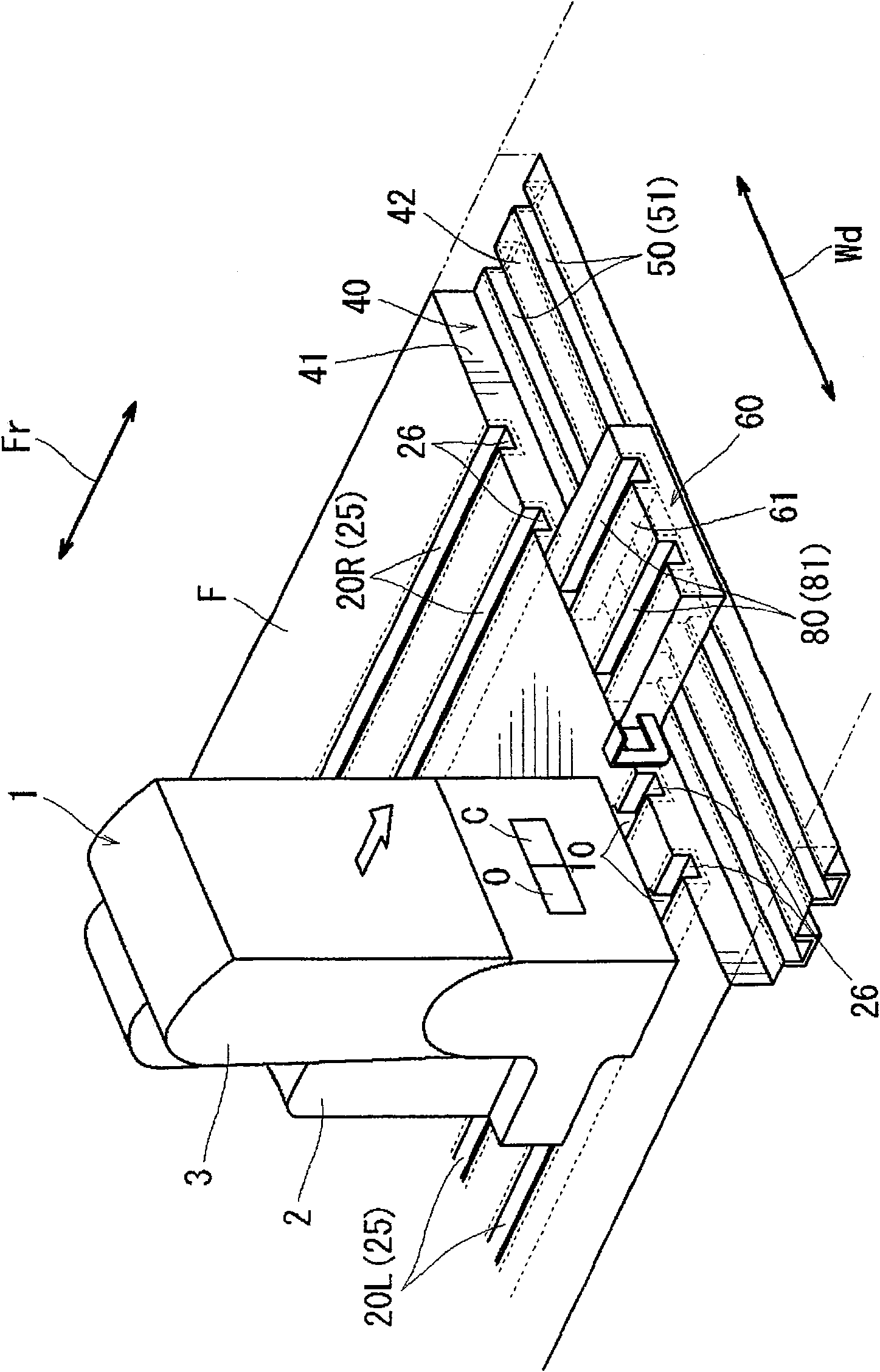
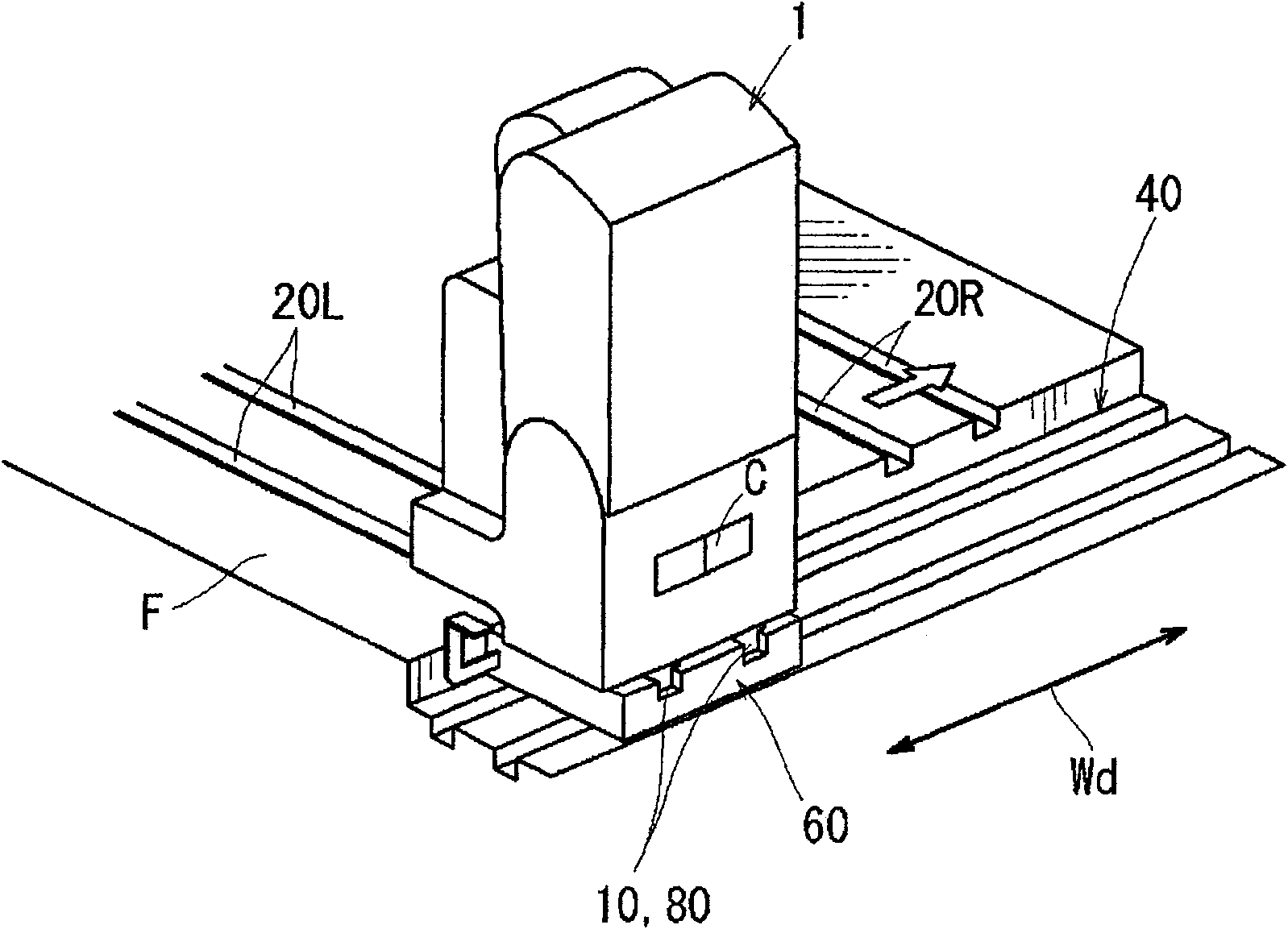
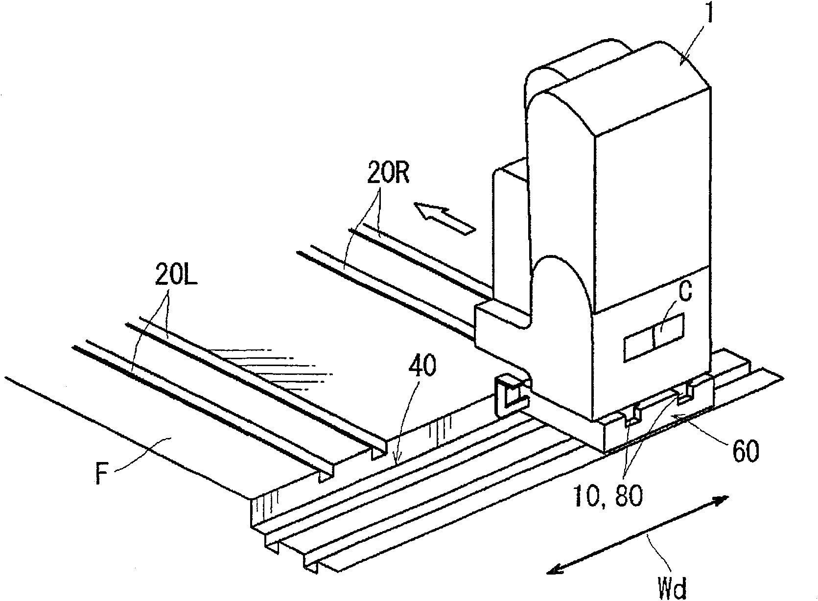
[0084] First, use Figure 1 to Figure 11 The vehicle seat moving device of the first embodiment will be described. figure 1 It is a perspective view showing a schematic configuration of a moving device for a vehicle seat. figure 2 It is a perspective view showing the state where the seat 1 is placed on the slide seat 60 . image 3 It means to make the sliding seat 60 from figure 2 The perspective view of the state of moving along the vehicle width direction Wd. Figure 4 It is a perspective view showing the state where the seat 1 is transferred to the lower rail 20R at the moving destination. Figure 5 It is a perspective view showing the state where all the correspondingly movable seats 1b-1f located on the left and right sides are assembled on one side lower rail 20R. Figure 6 It is a perspective view showing a state where the seat 1 is detached by detaching the upper rail 10 from the rear end side of the lower rail 20L. Figure 7 It is a perspective view showing the...

Embodiment 2

[0145] Next, use Figure 12 to Figure 17 A moving device for a vehicle seat according to Embodiment 2 will be described. Figure 12 It is a perspective view showing a schematic configuration of a moving device for a vehicle seat. Figure 13 It is an enlarged perspective view showing the structure of the slope 200 . Figure 14 It is a perspective view showing the state where the seat 1 is placed on the slide seat 60 . Figure 15 It is a perspective view which shows the state which moved the slide base 60 to the position where the slope 200 was provided. Figure 16 It is a perspective view showing a state where the seat 1 is detached from the vehicle floor F along the slope 200 . Figure 17 It is a structural diagram which shows the accommodation state of the slope 200.

[0146] In addition, in the present embodiment, substantially the same configurations and functional parts as those of the moving device for a vehicle seat shown in the first embodiment are given the same re...


PUM


Abstract

A movement device for a vehicle seat. Lower rails (20L, 20R) extending in a vehicle front-rear direction (Fw) are arranged in a vehicle width direction (Wd) on a vehicle floor (F). An upper rail (10)provided at a lower part of a seat (1) slidably engages with the lower rails (20L, 20R). A recess (40) is formed in the vehicle floor (F), enabling a carriage (60) to be conveyed between the lower rails (20L, 20R), in the vehicle width direction (Wd). The carriage (60) is constructed separated from the vehicle floor (F), and guide rails (80) are placed on the carriage. The guide rails (80) are disposed on lines that are extended from the lower rails (20L, 20R) so as to be able to directly receive sliding movement of the upper rail (10) that is detached from the lower rails (20L, 20R), in the direction of the extended lines.

Description

technical field [0001] The invention relates to a moving device for a vehicle seat. Specifically, it relates to a moving device for a vehicle seat that can move the seat in the front-rear direction and the vehicle width direction of the vehicle in order to change the seat arrangement of the vehicle seat. Background technique [0002] As a moving device for such a vehicle seat, for example, a technique disclosed in JP-A-2002-120604 is known. [0003] In this disclosed technology, a plurality of seats arranged on a vehicle floor are configured to be slidable along mesh-shaped slide grooves formed on the floor surface. Here, a pillar-shaped leg portion that is slidably engaged with the slide groove is attached to each seat. In addition, in order to connect the sliding movements of the seats, the sliding grooves are formed in the shape of an integrally connected mesh extending in the front-rear direction and the vehicle width direction of the vehicle. Thereby, the degree of f...

Claims


Application Information

Patent Timeline
Patent Type & Authority Patents(China)
IPC IPC(8): B60N2/06
CPCB60N2/01B60N2/0843B60N2/0705B60N2/062B60N2/0722B60N2002/0208B60N2/3047
Inventor 秋谷英纪贽正
Owner TOYOTA BOSHOKU KK
Why Eureka
Try Eureka