Method for sterilization, and eliminating accumulated calcium for electrobath

An electrolytic cell and voltage technology, applied in the direction of electrolysis process and electrolysis components, can solve the problems of easy calcium accumulation on the cathode plate, inconvenient use, and increased cost.

An electrolytic cell and voltage technology, applied in the direction of electrolysis process and electrolysis components, can solve the problems of easy calcium accumulation on the cathode plate, inconvenient use, and increased cost.

CN101003906BInactive Publication Date: 2010-05-12εΎζ–‡ζ˜Ÿ

Image

  • Method for sterilization, and eliminating accumulated calcium for electrobath
  • Method for sterilization, and eliminating accumulated calcium for electrobath
  • Method for sterilization, and eliminating accumulated calcium for electrobath

Examples


Embodiment Construction

[0020] In order to make those skilled in the art easily understand the content of the device of the present invention and the beneficial effects that can be achieved, a specific embodiment is now listed, and the detailed description is as follows in conjunction with the accompanying drawings:

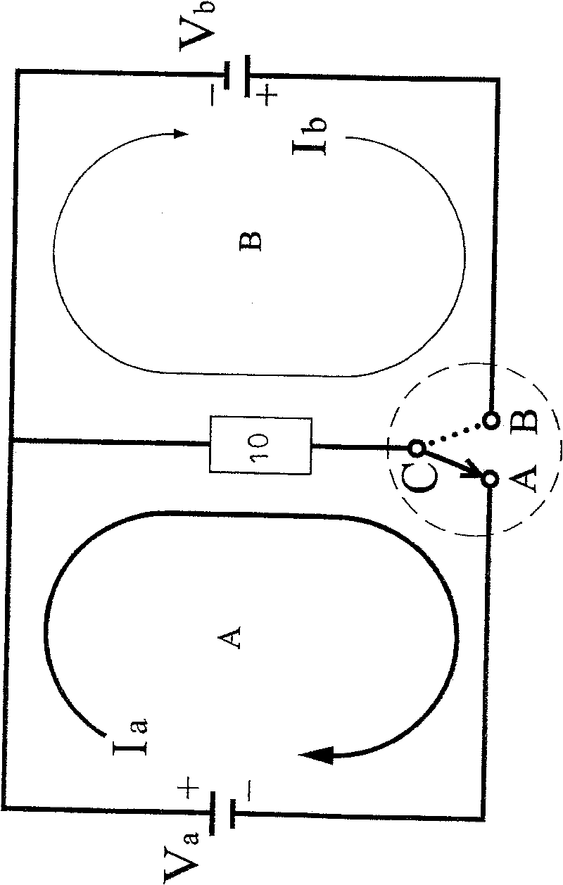
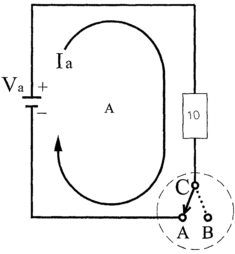
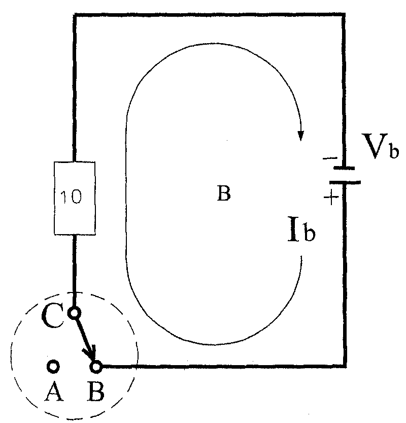
[0021] A method for sterilization and removal of calcium deposits in an electrolyzer, please refer to figure 1 , figure 1 Shown is a schematic circuit diagram of the present invention. The main reason is that the electroanalysis circuit (electroanalysis circuit) A of the electrolytic cell (electrode chamber) 10 is applied with a generally normal working voltage, and an electronic fast switching switch (electronic instant switch) C is used to select the electroanalysis circuit (electroanalysis circuit) A (such as figure 2 Shown: electrolytic circuit schematic diagram of the present invention) or pulse high voltage circuit (highvoltage pulsecircuit) B (as image 3 Shown: the schematic ...


PUM


Abstract

This invention discloses a method for sterilizing and removing residual calcium from electrolytic tank. The method applies an instant reverse pulse wave multi-times the practicle working voltage to the electrolytic tank during the electrolysis process. The pulse wave voltage has potential difference enough to kill bacteria and viruses, and can vibrationally remove CaCO3 and other types of calciumdeposited onto the cathode plate, thus can avoid crystal deposition.

Description

technical field [0001] The invention relates to a method for sterilizing an electrolyzer and removing calcium deposits, in particular to a technique for sterilizing an electrolyzer for electrolyzing water and removing calcium deposits. Background technique [0002] Usually, the traditional commonly used electrolyzers generally have the problems of inability to sterilize and the cathode plate is easy to accumulate calcium. To solve the problem of sterilization, ultraviolet lamps or microporous filter materials are generally used to achieve the purpose of sterilization or filter bacteria. To solve the problem of calcium accumulation, it is to use reverse polarity voltage to remove calcium accumulation, or soak food grade citric acid or acetic acid for cleaning. [0003] However, the use of ultraviolet lamps to sterilize or any bacteria-filtering materials will increase the cost of implementation, which is not economical, and the application of reverse polarity voltage will cau...

Claims


Application Information

Patent Timeline
12 May 2010
Publication
CN101003906B
IPC
C25B15/00
Inventors
εΎζ–‡ζ˜Ÿ