
Fan salt spray proofing structure and fan frame with same

An anti-salt spray and fan technology, applied in the components of the pumping device for elastic fluids, non-variable-capacity pumps, machines/engines, etc., can solve the problems of low heat dissipation efficiency, short life, fan damage, etc. Life-enhancing effect

Active Publication Date: 2015-05-06
ASIA VITAL COMPONENTS SHENZHEN CO LTD
View PDF5 Cites 0 Cited by
  • Summary
  • Abstract
  • Description
  • Claims
  • Application Information

AI Technical Summary

Problems solved by technology

[0002] With the continuous expansion of the application field of cooling fans, from CPu in electronic equipment, servers, power supplies, communication chassis, telecommunication base stations, etc., the environment in which fans are used is getting worse and worse; In the environment, when the fan is running, a vortex will be formed at the bottom of the fan frame after the wind flows through the fan blades and the hub. If the fan is placed in a harsh environment, crystallization may occur between the hub and the fan blades. The structure is protected from water vapor and salt spray intrusion, so when the internal stator and bearings are invaded by water vapor and salt spray, they will be rusted, and the circuit board will be corroded and damaged, so the life of the fan will be shortened
[0003] The current cooling fan is mainly composed of stator, rotor, circuit board, fan blade body and fan frame and other components, and in order for the fan to operate normally in the aforementioned harsh environment, it is necessary to prevent salt spray and water vapor from corroding the inside of the fan. Structure, in the prior art, in order to prevent water vapor and salt mist from corroding the internal stator and circuit board of the fan and causing damage to the fan, the aforementioned stator group and circuit board are glued to the outside of the stator group and circuit board The complete coating is used to prevent water vapor and salt spray from damaging the stator group and circuit board; however, although the aforementioned glue sealing method is effective to prevent water vapor and salt spray, it is easy to prevent heat dissipation after the stator group and circuit board are completely sealed and operated. The phenomenon of heat accumulation; so the prior art has the following disadvantages:
[0004] 1. Short life;
[0005] 2. The inside of the fan is easy to accumulate heat;
[0006] 3. Low cooling efficiency

Method used


Image

  • Fan salt spray proofing structure and fan frame with same
  • Fan salt spray proofing structure and fan frame with same
  • Fan salt spray proofing structure and fan frame with same

Examples


Embodiment Construction

[0037] Below in conjunction with accompanying drawing and specific embodiment the present invention is described in further detail:

[0038] The above-mentioned purpose of the present invention and its structural and functional characteristics will be described according to the preferred embodiments of the accompanying drawings.

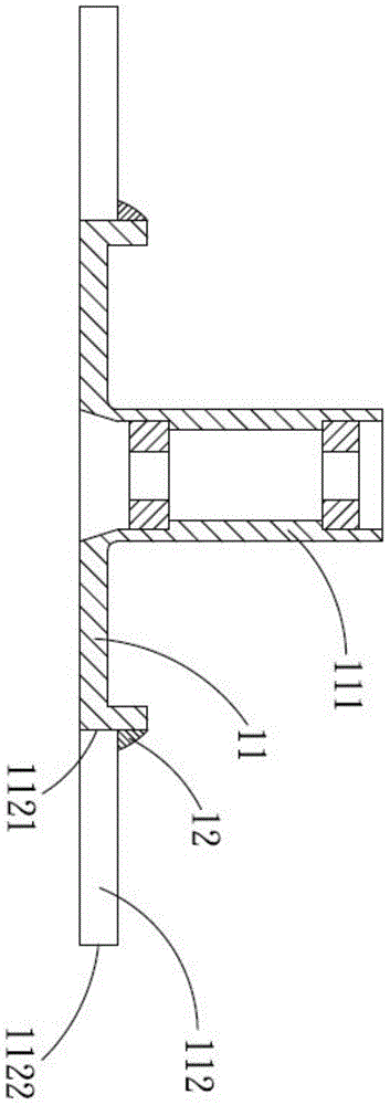
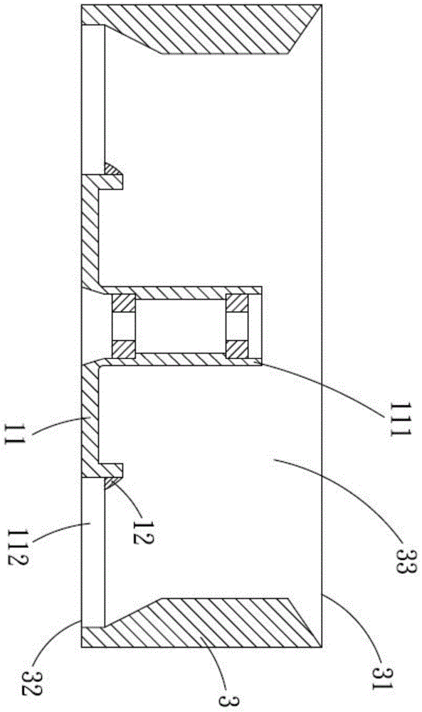
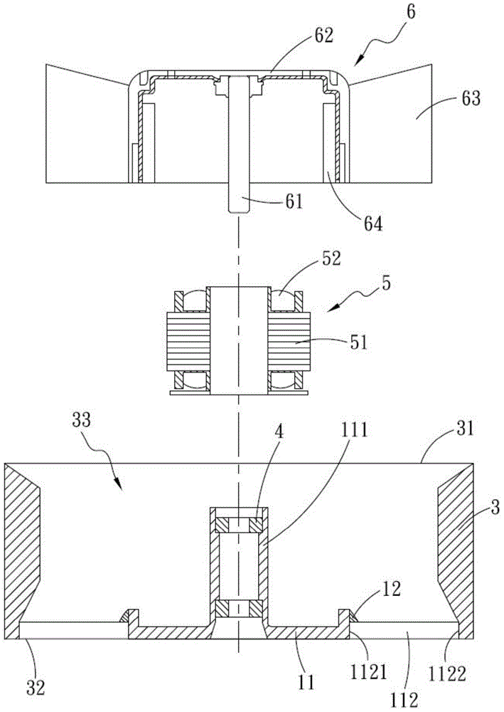
[0039] see figure 1 , is a cross-sectional view of the first embodiment of the present invention, as shown in the figure, the fan anti-salt spray structure includes: a base 11, a diversion convex body 12;

[0040] The base 11 is vertically provided with a shaft tube 111 , the shaft tube 111 is configured by extending from one side of the base 11 perpendicular to the direction opposite to the base 11 , and the base 11 extends outwards with a plurality of connecting bodies 112 .

[0041] The diversion protrusion 12 is located at the connection between the base 11 and the connecting body 112 .

[0042] The connecting body 112 is any one of a fan vane ...


PUM


Abstract

The invention relates to a fan salt spray proofing structure and a fan frame with the structure. The fan salt spray proofing structure comprises a base and at least one flow guide protrusion; the base is perpendicularly provided with a beam barrel, and the base extends outwards to form a plurality of connecting bodies; and the flow guide protrusions are arranged at the connecting positions of the base and the connecting bodies. In addition, the fan frame is provided with a body, and the body is provided with a first open side and a second open side; and a flow way is jointly defined by the first open side and the second open side. One end of each connecting body is connected with the second open end of the corresponding body; through arrangement of the flow guide protrusions, deposition crystallization caused by the vortex formed by flowing of airflow containing moisture and salt spray through the base and the connecting bodies can be avoided; and the service life of a fan is greatly prolonged.

Description

technical field [0001] The invention relates to a fan salt spray structure and a fan frame thereof, in particular to a fan salt spray structure and a fan frame capable of preventing salt spray from depositing inside the fan and improving the service life of the fan. Background technique [0002] With the continuous expansion of the application field of cooling fans, from CPu in electronic equipment, servers, power supplies, communication chassis, telecommunication base stations, etc., the environment in which fans are used is getting worse and worse; In the environment, when the fan is running, a vortex will be formed at the bottom of the fan frame after the wind flows through the fan blades and the hub. If the fan is placed in a harsh environment, crystallization may occur between the hub and the fan blades. The structure is protected from water vapor and salt mist intrusion, so when the internal stator and bearings are invaded by water vapor and salt mist, they will be rus...

Claims


Application Information

Patent Timeline
Patent Type & Authority Applications(China)
IPC IPC(8): F04D29/00F04D29/52
CPCF04D29/002F04D29/522
Inventor 刘昶贤
Owner ASIA VITAL COMPONENTS SHENZHEN CO LTD
Learn More