Hollow member of concrete

An emptying and component technology, applied in building components, building structures, floors, etc., can solve the problems of easy dislocation, inconvenient positioning, affecting the construction quality and construction efficiency of hollow floors

Inactive Publication Date: 2007-10-17
湖南邱则有专利战略策划有限公司
View PDF2 Cites 3 Cited by
  • Summary
  • Abstract
  • Description
  • Claims
  • Application Information

AI Technical Summary

Problems solved by technology

However, when this kind of thin-walled box is used as an empty core formwork, it needs to be constructed individually, and it is inconvenient to locate each other, and it is prone to misalignment, which affects the construction quality and efficiency of the hollow floor. The force-bearing and force-transmitting components of the cover, especially when the size of the hollow formwork is large, are more obvious. Therefore, it is urgent to develop a new type of hollow component for concrete.

Method used


Image

  • Hollow member of concrete
  • Hollow member of concrete
  • Hollow member of concrete

Examples


Embodiment Construction

[0059] The present invention will be further described below in conjunction with the accompanying drawings and embodiments.

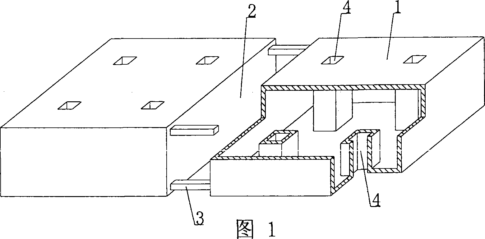
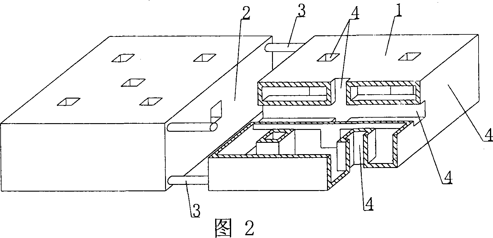
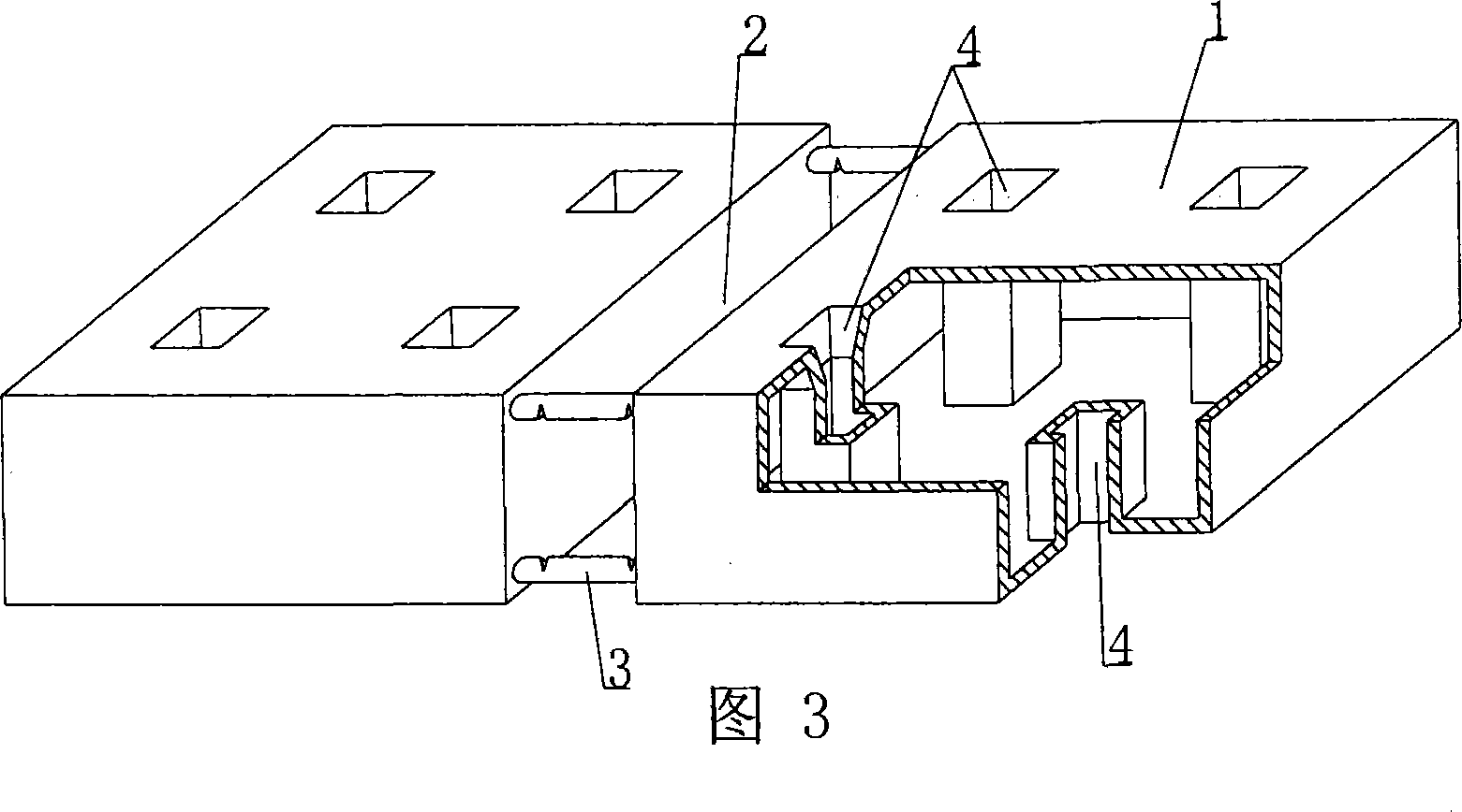
[0060] As shown in the accompanying drawings, the present invention includes fasting formwork 1, which is characterized in that at least two fasting formworks 1 are arranged alternately, and the opposite surfaces of the fasting formwork 1 form a cast-in-situ concrete inner rib cavity 2, and the inner rib cavity 2, there is at least one spacing support member 3 that connects the hollow formwork 1 on the opposite or adjacent surface into one, and each hollow formwork 1 has a hole 4 for pouring in-situ concrete that runs through the hollow formwork 1. upper and lower surfaces. Fig. 1 is a schematic structural diagram of Embodiment 1 of the present invention. In the accompanying drawings, 1 is an empty stomach formwork, 2 is an inner rib cavity, 3 is a spacer brace, and 4 is a hole. In each accompanying drawing, those with the same number have the same des...


PUM


Abstract

A hollow component for concrete includes a hollow mould shell (1), characterized in that at least two hollow mould shells (1) are spacingly arranged, a cast-in-situ concrete inner rib mould cavity (2) is constructed between the opposite faces of the hollow mould shells (1), at least one space drawing part (3) for interphasely connecting the opposite or neighboring solid and light material components of polyhedron (1) to an integer is provided in the inner rib mould cavity (2), one pore space (4) for casting the reinforced concrete cast-in-situ throughout upper and lower surfaces of the hollow mould shells (1) is provided on each hollow mould shell. The hollow component for concrete is adapted to use for hollow bridge, wall body, basic slab, room cover and hollow building cover of various of reinforced concrete cast-in-situ or prestressed reinforced concrete, especially use for the hollow building cover without beam.

Description

[0001] This application is a divisional application of an invention patent application with an application date of July 7, 2003, an application number of 03147336.9, and a title of "a hollow member for concrete". (1) Technical field [0002] The invention relates to a hollow component for concrete. (2) Background technology [0003] At present, the cast-in-place reinforced concrete hollow floor is a widely used floor structure, which has the advantages of fast construction speed, small structural height, flexible division of indoor areas, and no need for ceiling decoration. The lightweight permanent tire molds filled with it are available in various hollow tubes and boxes, hollow or solid. For example, the patent No. ZL99232921.3, which the applicant applied for on March 10, 1999, is a utility model patent named "thin-walled tube for filling cast-in-place reinforced concrete", which consists of a hard thin-walled tube and two plugs. It is used as a lightweight permanent tir...

Claims


Application Information

Patent Timeline
Patent Type & Authority Applications(China)
IPC IPC(8): E04B5/36E04B5/18E04C1/00
Inventor 邱则有
Owner 湖南邱则有专利战略策划有限公司
Why Eureka
Try Eureka