Medicine liquid flow rate controller for infusion set
A technology of flow rate control device and infusion set, which is applied in the direction of flow control, non-electric variable control, control/regulation system, etc. It can solve the problems of accurate control of liquid medicine and achieve the effects of uniform flow speed, simple overall structure and simple operation
- Summary
- Abstract
- Description
- Claims
- Application Information
AI Technical Summary
Problems solved by technology
Method used
Image
Examples
Embodiment 1
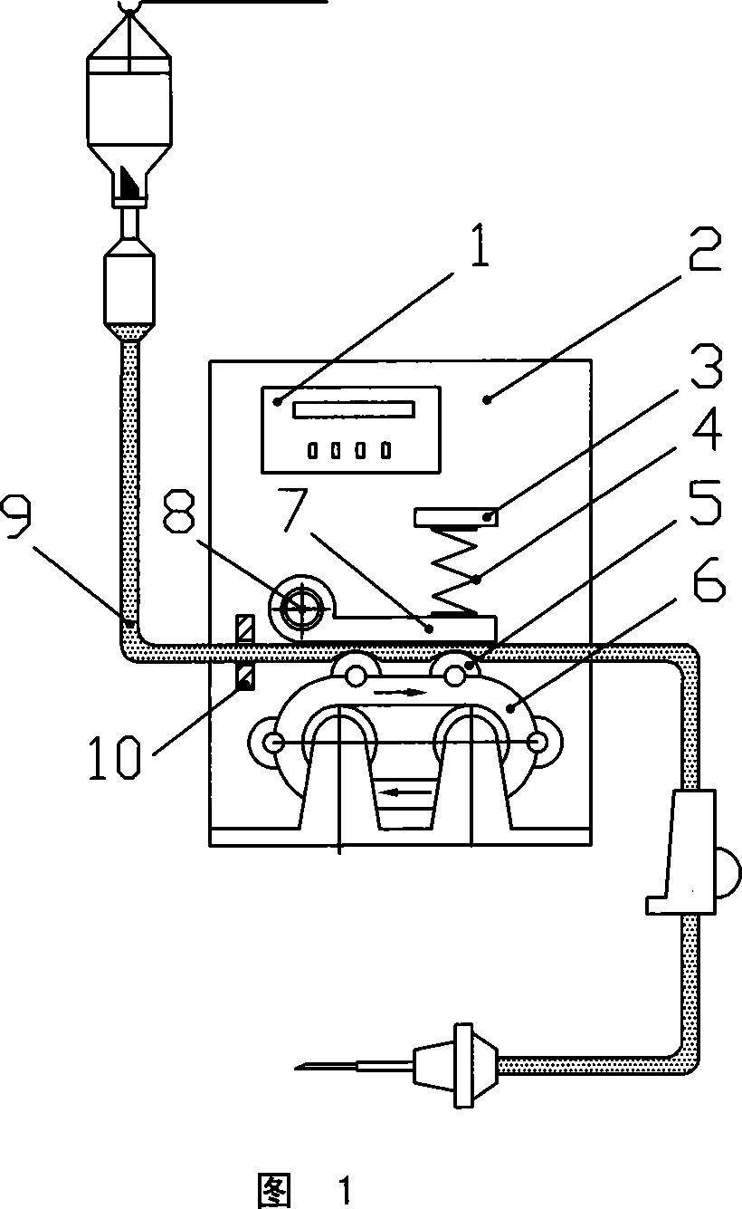
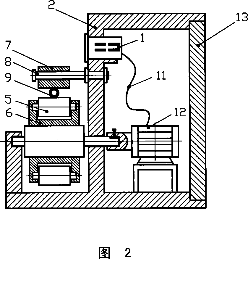
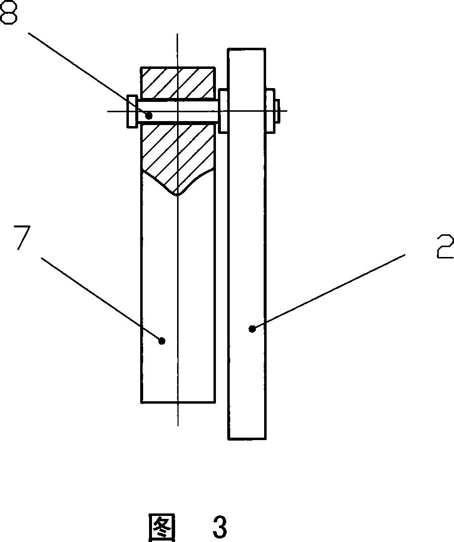
[0024] As shown in Figures 1-4, the present embodiment includes a casing 2, which includes a cavity with a motor 12 and a control instrument 1 connected to the motor 12 through a wire 11 fixed on the casing 2. There is a bracket on the outside of the cavity, and the flow booster 6 is installed on the bracket. The flow pusher 6 includes two rotating shafts, one of which is connected to the motor 12 . Crawler belts are installed on the rotating shaft, and a group of rollers 5 are installed on the crawler belts through shaft intervals. A pressure plate 7 is installed on the casing 2 on the same side as the two rotating shafts above the pusher 6. One end of the pressing plate 7 is connected with the casing 2 through a positioning shaft 8 parallel to the rotating shaft, and the other end is matched with the lower end of the spring 4. The upper end of the spring 4 It is fixed on the plate body fixedly connected with the casing 2. A tube clip 10 is provided on one side of the casin...
Embodiment 2
[0027] As shown in Figures 5-8, this embodiment includes a casing 2, and the casing 2 includes a cavity with a bracket outside the cavity on which a flow booster 6 is installed. The flow mover 6 includes a circular support with a rotating shaft, a group of rollers 5 are installed at intervals through the shaft in the groove on the side of the support, and a pressing plate 7 is installed on the casing 2 above the flow mover 6 . The part corresponding to the flow booster 6 on the lower surface of the pressing plate 7 is arc-shaped, its curvature is smaller than that of the circular support, and its span is greater than the diameter of the circular support. One end of the pressing plate 7 is connected with the casing 2 through a shaft parallel to the rotating shaft, and the other end cooperates with the lower end of the spring 4 , and the upper end of the spring 4 is fixed on the plate body fixedly connected with the casing 2 . A tube clip 10 is provided on one side of the casing...
Embodiment 3
[0029] As shown in Figures 9 and 10, the embodiment includes a casing 2, on which there is a bracket on which a flow booster 6 is installed, and the structure of the flow booster 6 is the same as that of the first embodiment. Positioning chute 14 is fixed on the casing 2 on flow booster 6 one side, and slide block is housed in the groove, and the slide block top cooperates with spring, and the upper end of spring is connected with the plate body that is fixed on the casing. Other parts of this embodiment are the same as those of Embodiment 1, and will not be repeated here.
PUM
 Abstract
Description
Claims
Application Information
 - R&D
- Intellectual Property
- Life Sciences
- Materials
- Tech Scout
- Unparalleled Data Quality
- Higher Quality Content
- 60% Fewer Hallucinations
Browse by: Latest US Patents, China's latest patents, Technical Efficacy Thesaurus, Application Domain, Technology Topic, Popular Technical Reports.
© 2025 PatSnap. All rights reserved.Legal|Privacy policy|Modern Slavery Act Transparency Statement|Sitemap|About US| Contact US: help@patsnap.com


