Medicine liquid flow rate controller for infusion set

A technology of flow rate control device and infusion set, which is applied in the directions of flow control, non-electric variable control, control/regulation system, etc., can solve problems such as accurate control of medicinal liquid, and achieve the effects of uniform flow speed, accurate measurement and simple overall structure

Inactive Publication Date: 2009-07-08
闫云涛
View PDF15 Cites 0 Cited by
  • Summary
  • Abstract
  • Description
  • Claims
  • Application Information

AI Technical Summary

Problems solved by technology

[0003] The present invention aims at the technology of manually adjusting the flow regulator carried by the infusion set itself or relying on the existing flow rate control device of the infusion set to adjust the flow rate of the liquid when the disposable infusion set is used in the market to infuse the patient. Can not be designed for the problem of accurate control of the flow rate of the liquid medicine in the disposable infusion set, the purpose of the present invention is to provide a common infusion set with low cost and to control the infusion set outside the infusion set hose. Infusion set medical liquid flow rate control device that can accurately control the flow rate of the liquid medicine

Method used


Image

  • Medicine liquid flow rate controller for infusion set
  • Medicine liquid flow rate controller for infusion set
  • Medicine liquid flow rate controller for infusion set

Examples


Embodiment 1

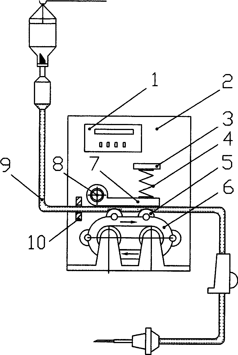
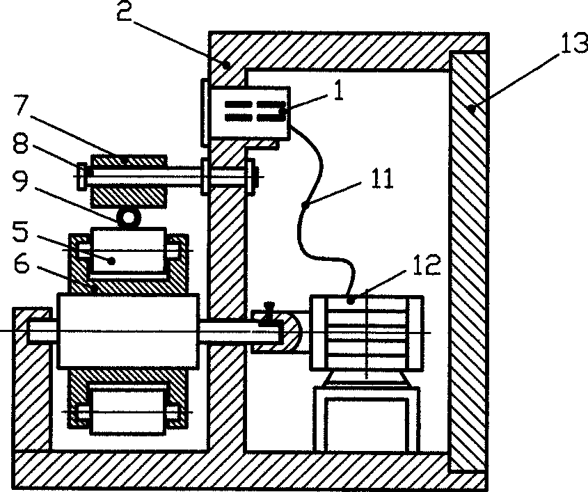
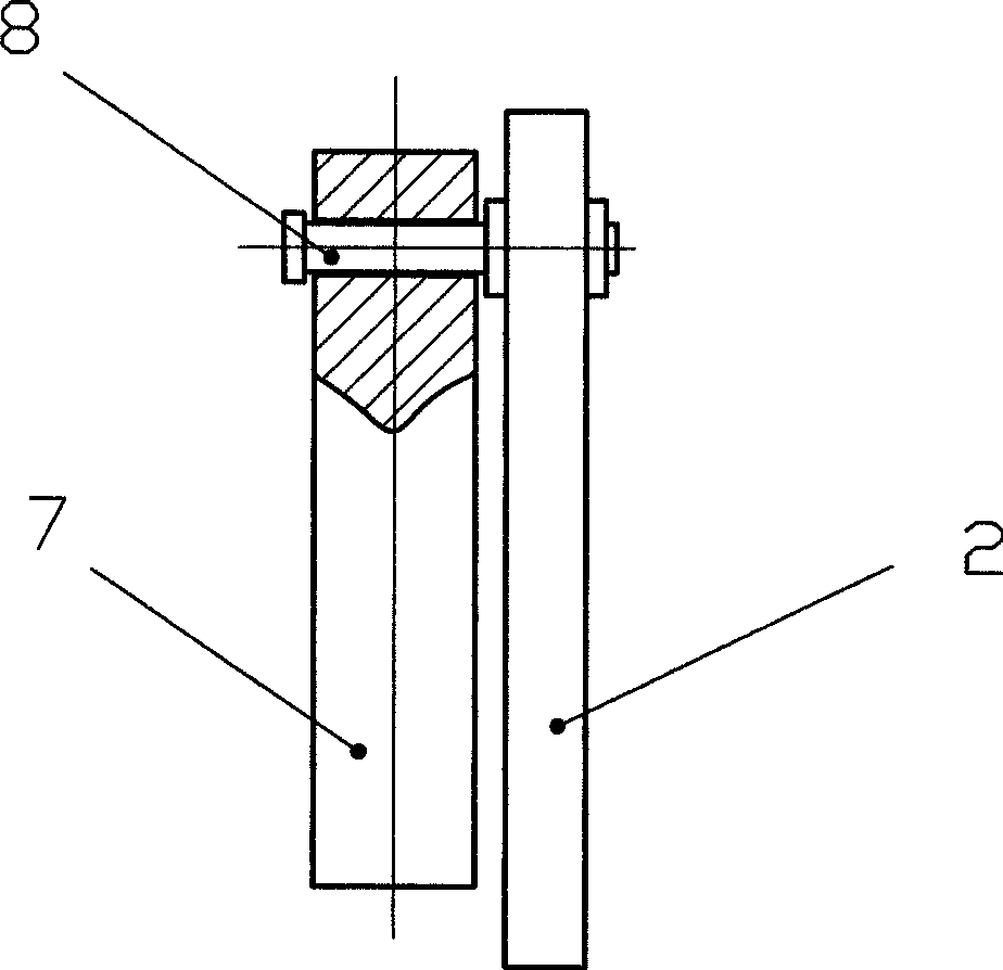
[0024] Such as Figure 1-4 As shown, the present embodiment includes a casing 2, and the casing 2 includes a cavity in which there is a motor 12, and a control instrument 1 connected to the motor 12 through a wire 11 is fixed on the casing 2. There is a bracket on the outside of the cavity, and the flow booster 6 is installed on the bracket. The flow pusher 6 includes two rotating shafts, one of which is connected to the motor 12 . Crawler belts are installed on the rotating shaft, and a group of rollers 5 are installed on the crawler belts through shaft intervals. A pressure plate 7 is installed on the casing 2 on the same side as the two rotating shafts above the pusher 6. One end of the pressing plate 7 is connected with the casing 2 through a positioning shaft 8 parallel to the rotating shaft, and the other end is matched with the lower end of the spring 4. The upper end of the spring 4 It is fixed on the plate body fixedly connected with the casing 2. A tube clip 10 is...

Embodiment 2

[0027] Such as Figure 5-8 As shown, this embodiment includes a casing 2, and the casing 2 includes a cavity, and a bracket is arranged outside the cavity, and a flow pusher 6 is installed on the bracket. The flow mover 6 includes a circular support with a rotating shaft, a group of rollers 5 are installed at intervals through the shaft in the groove on the side of the support, and a pressing plate 7 is installed on the casing 2 above the flow mover 6 . The part corresponding to the flow booster 6 on the lower surface of the pressing plate 7 is arc-shaped, its curvature is smaller than that of the circular support, and its span is greater than the diameter of the circular support. One end of the pressing plate 7 is connected with the casing 2 through a shaft parallel to the rotating shaft, and the other end cooperates with the lower end of the spring 4 , and the upper end of the spring 4 is fixed on the plate body fixedly connected with the casing 2 . A tube clip 10 is provid...

Embodiment 3

[0029] Such as Figure 9 , 10 As shown, the embodiment includes a casing 2, on which there is a bracket, on which a flow pusher 6 is installed, and the structure of the flow pusher 6 is the same as that of the embodiment 1. Positioning chute 14 is fixed on the casing 2 on flow booster 6 one side, and slide block is housed in the groove, and the slide block top cooperates with spring, and the upper end of spring is connected with the plate body that is fixed on the casing. Other parts of this embodiment are the same as those of Embodiment 1, and will not be repeated here.


PUM


Abstract

The invention relates to a device for controlling the liquid flow rate of an infusion set. It consists of a casing and a pusher with rollers installed on the casing. The extrusion mechanism that cooperates with the roller of the flowmeter is installed on the casing through a positioner that is parallel to the roller. The movable part is connected with an elastic object fixedly connected with the casing at one end. The invention has the characteristics of simple operation, accurate measurement, simple overall structure and low manufacturing cost.

Description

technical field [0001] The invention relates to a device for controlling the liquid flow rate of an infusion set. Background technique [0002] Intravenous infusion is one of the most commonly used clinical treatment methods, and it is a common drug administration technique in the nursing profession. Clinically, the appropriate infusion speed is matched according to the different drugs and patient conditions. Some special patients or special drugs in the hospital must require a small amount of low-speed accurate infusion, otherwise, if the infusion is too fast, it may cause poisoning, and in more severe cases, edema and heart failure may occur; if the infusion is too slow, the dose may not be enough , compromising treatment and placing an unnecessary burden on patients and care. Routine clinical infusion, generally adopts disposable infusion device hanging bottle infusion, and observes with eyes, relies on regulating the flow regulator to control the speed of medicine drip...

Claims


Application Information

Patent Timeline
Patent Type & Authority Patents(China)
IPC IPC(8): A61M5/168A61M5/14
Inventor 闫云涛
Owner 闫云涛
Why Eureka
Try Eureka