Mechanical switching contact

A contact point, mechanical technology, applied in the direction of electrical components, electrical switches, circuits, etc., to achieve the effect of reducing contact bounce and high contact pressure

Inactive Publication Date: 2007-11-28
MASCHFAB REINHAUSEN GEBR SCHEUBECK GMBH & CO KG
View PDF0 Cites 4 Cited by
  • Summary
  • Abstract
  • Description
  • Claims
  • Application Information

AI Technical Summary

Problems solved by technology

[0003] This mechanical transfer contact has proven to be feasible in practical applications, but it has disadvantages in the case of very high current double pole interruption

Method used


Image

  • Mechanical switching contact
  • Mechanical switching contact
  • Mechanical switching contact

Examples


Embodiment Construction

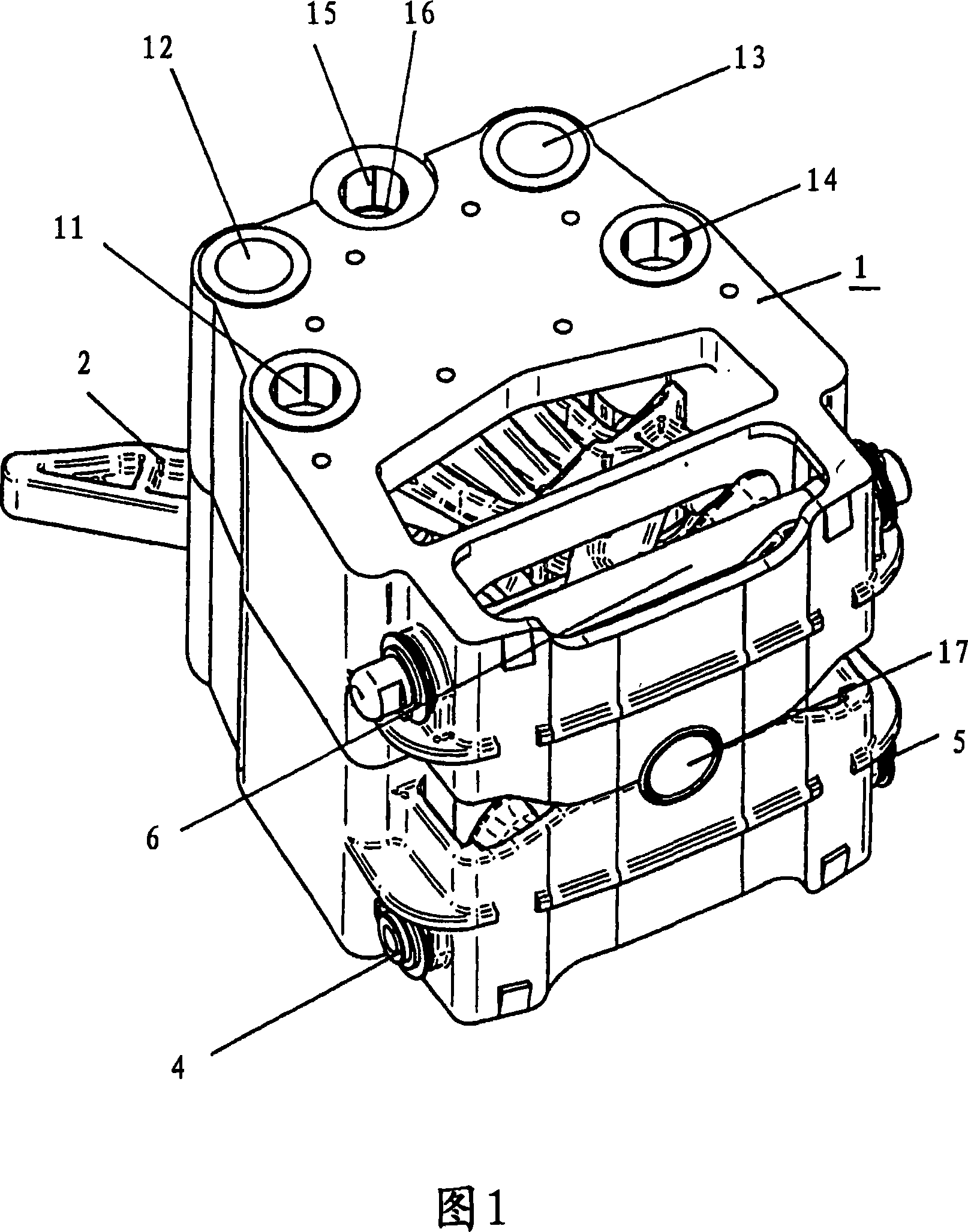
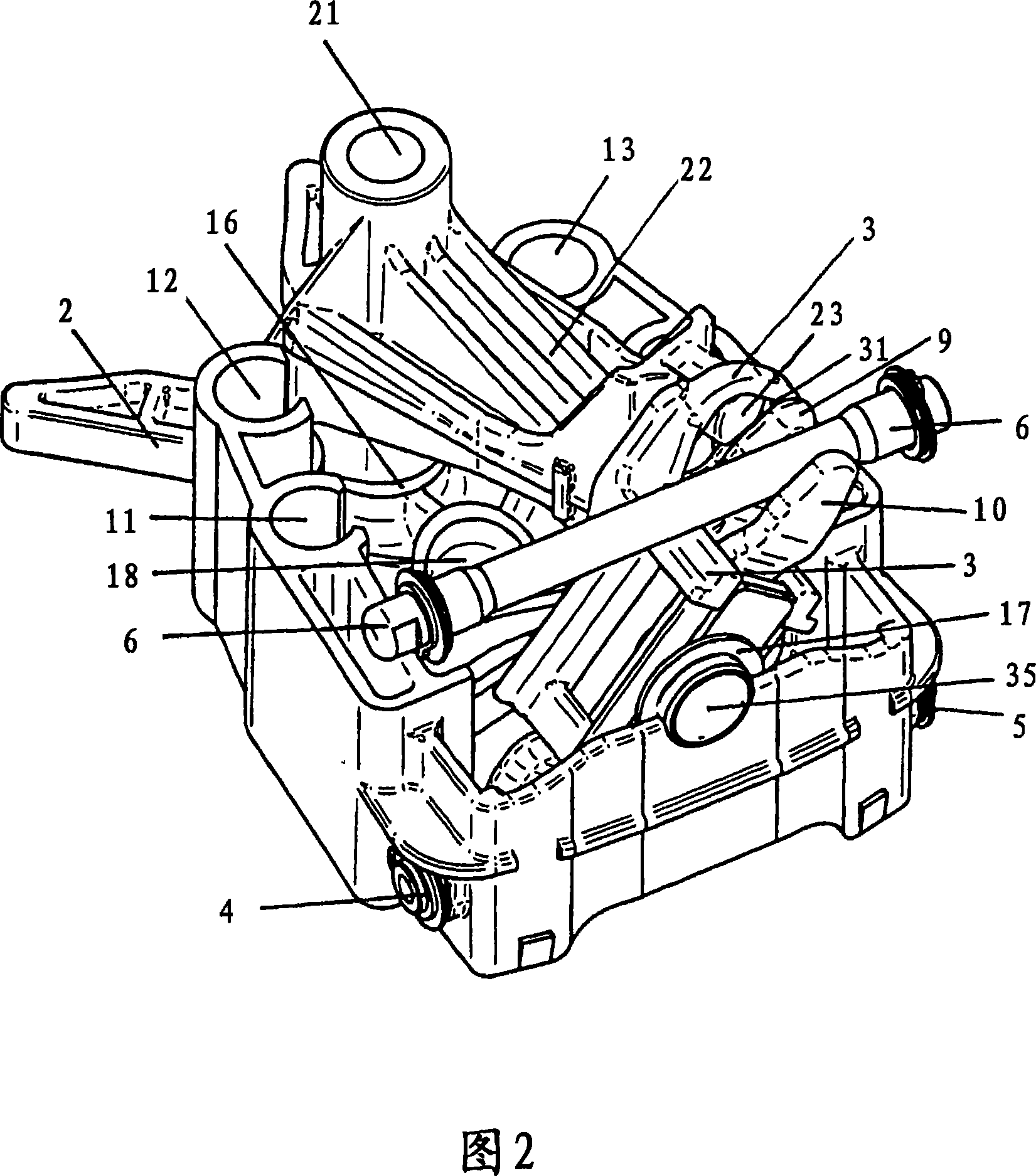
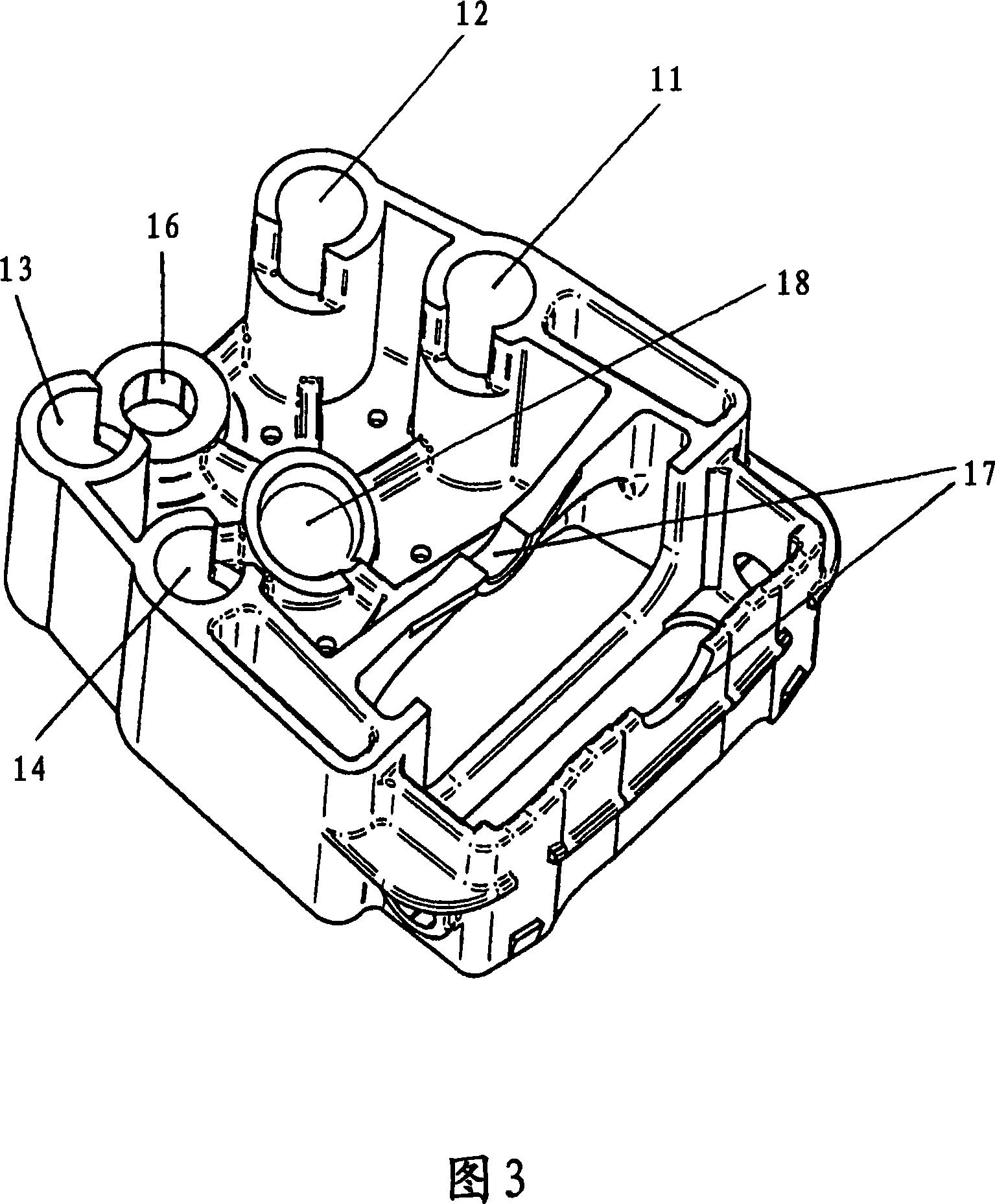
[0016] First, the mechanical switching contact according to the invention shown in FIGS. 1 and 2 will be explained in detail. It has a two-part insulating material carrier 1 which accommodates the other components explained below and encloses the entire arrangement. In FIG. 2 the upper part of the insulating material carrier 1 is omitted in order to better illustrate the internal components. The insulating material support 1 is provided with longitudinal holes 11 to 14 extending in each profiled rod, which will be explained in more detail below. In the region of the other longitudinal bore 15 is arranged a bearing 16 in which the actuating rod 2 is mounted rotatably by means of a bearing cap screw (not shown). A further bearing 17 is arranged laterally, which accommodates a contact housing 3 which will be explained in more detail below. Finally, a spherical segment-shaped receptacle 18 is also provided on the insulating material carrier 1 , in which the compression spring 8 ...


PUM


Abstract

The invention relates to a mechanical switching contact having an insulating material support (1), on which fixed contacts (4, 5, 6) are arranged. Furthermore, a switching lever (2) is mounted such that it can rotate on the insulating material support (1) and has a pivoting arm (22). In addition, a pivotable contact housing (3) is also mounted on the insulating material support (1), which contact housing bears parallel contact fingers (9, 10), which surround the respectively connected fixed contacts (4, 5, 6) on both sides when contact is made.

Description

technical field [0001] The invention relates to a mechanical changeover contact (Schaltkontakt) for changeover in the case of a changeover switch of an on-load tap changer (Stufenschalter). Background technique [0002] A mechanical switching contact for double-pole interruption for an on-load tap-changer is known, for example, from DE-PS 100 50 821 C1. This known mechanical switching contact has an insulating material carrier, on which the fixed contact is arranged, the fixed contact having a ball-shaped contact area. Furthermore, a contact carrier is rotatably mounted on this insulating material carrier, which is connected to a swivel arm which can be swiveled by an angle. On the free end of the swivel arm is fastened a contact piece which has two contact wheels at its two ends. The fixed contacts are selectively made through contact wheels. Depending on the position of the swivel arm, the contact wheel acts on the spherical surface of the respective oppositely arranged...

Claims


Application Information

Patent Timeline
Patent Type & Authority Applications(China)
IPC IPC(8): H01H9/00
CPCH01H9/0016H01H9/00
Inventor G·克洛特S·弗雷德
Owner MASCHFAB REINHAUSEN GEBR SCHEUBECK GMBH & CO KG
Why Eureka
Try Eureka