Micro-electro-mechanical system and method for producing the same

a micro-electromechanical and mechanical system technology, applied in mechanical apparatus, engine components, relays, etc., can solve the problems of comparatively low force obtained by the devices described so far, and the control of the control of the individual beam elements is complicated

Active Publication Date: 2016-12-01
FRAUNHOFER GESELLSCHAFT ZUR FOERDERUNG DER ANGEWANDTEN FORSCHUNG EV
View PDF0 Cites 3 Cited by
  • Summary
  • Abstract
  • Description
  • Claims
  • Application Information

AI Technical Summary

Benefits of technology

[0017]It is the core idea of the present invention to have found out that the above object, such as increasing mechanical contact forces and / or simplifying the control can be obtained by increasing an area of piezo-active materials and reducing a proportion of dimensions, such as between length and width of the actuator and that further a deflectable actuator plate which effects, in one of her operating states, a hollow warp along two linearly independent spatial directions increases the contact forces further, such that transversal contractions in the piezoelectric functional area can be used.
[0018]By converting the transversal contractions of the piezoelectric functional area into a hollow warp in addition to a curvature in a direction which is linearly independent to a direction of the transversal contraction, apart from an actuator force, increased structural rigidity can be used for establishing a contact, such that contact forces are increased and / or contact bouncing of the mechanical contacts can be reduced.
[0020]It is an advantage of this embodiment that based on the hollow warp a contact force between abutment area and deflectable actuator plate can be great with respect to a beam element and at the same time simple control of the piezoelectric functional layer is enabled, for example by two operating states “controlled (on)” and “non-controlled (off)”.
[0022]It is an advantage of this embodiment that an ellipse enables a formation of the active area and hence an effectuation of the hollow warp along two linearly independent directions.

Problems solved by technology

However, there are only a few commercial applications in niche markets, such as high-frequency measurement technology or the military.
The forces obtained by the devices described so far are, however, comparatively low.
However, this necessitates complicated control of the individual beam elements.

Method used


Image

  • Micro-electro-mechanical system and method for producing the same
  • Micro-electro-mechanical system and method for producing the same
  • Micro-electro-mechanical system and method for producing the same

Examples


Embodiment Construction

[0046]Before embodiments of the present invention will be discussed in detail based on the drawings, it should be noted that identical, functionally equal or equal elements, objects and / or structures are provided with the same reference numbers in the different figures, such that the description of these elements illustrated in different embodiments is interchangeable or can be applied to each other.

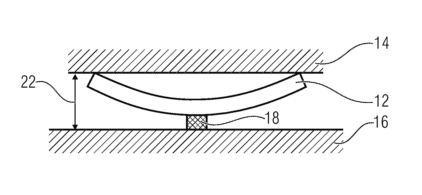
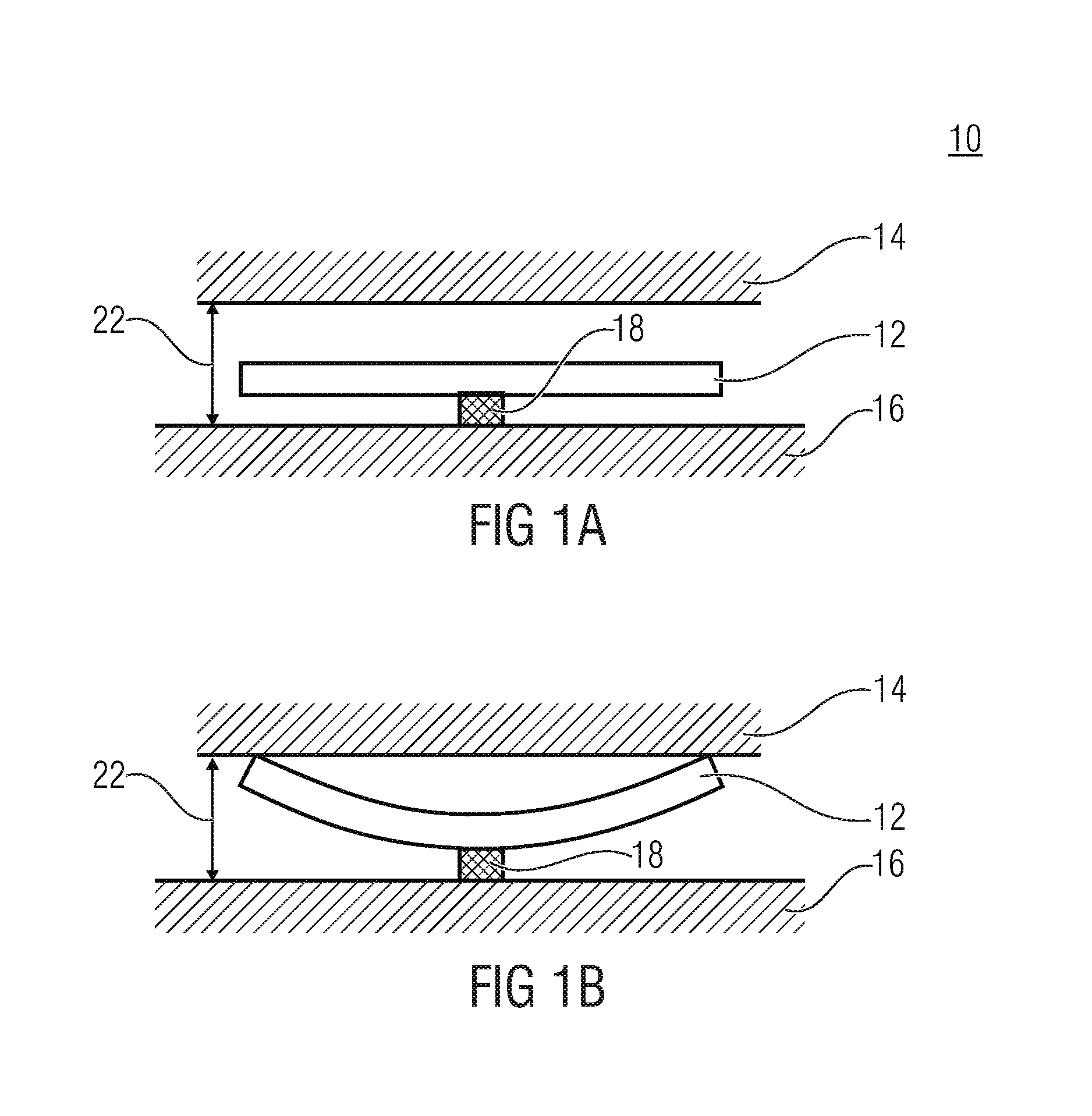
[0047]A state where an electric voltage is applied to a piezoelectric functional layer will be referred to as “on” or “on-state”. A state where the piezoelectric functional layer is without voltage will be referred to below as “off” or “off-state”. The following discussions describe deflectable actuator plates such that the same are configured to effect a hollow warp and to provide mechanical contact to an abutment area in the on-state and to be spaced apart from the abutment area in the off-state. It is obvious that based on mechanical pretensions or electrical bias in the piezoelectric...


PUM


Abstract

A micro-electro-mechanical system includes a deflectable actuator plate and an abutment area. An integral piezoelectric functional layer of the deflectable actuator plate is configured across an area APS of the actuator plate. The deflectable actuator plate is configured to effect a hollow warp in at least a controlled or non-controlled state, wherein the abutment area is disposed facing a hollow side of the deflectable actuator plate defined by the hollow warp. The deflectable actuator plate is configured to provide, in the state in which the same effects the hollow warp, mechanical contact between the deflectable actuator plate and the abutment area. In the other state, the deflectable actuator plate is disposed spaced apart from the abutment area.

Description

CROSS-REFERENCE TO RELATED APPLICATIONS[0001]This application is a continuation of copending International Application No. PCT / EP2015 / 052983, filed Feb. 12, 2015, which claims priority from German Application No. 10 2014 202 763.2, filed Feb. 14, 2014, which are each incorporated herein in its entirety by this reference thereto.BACKGROUND OF THE INVENTION[0002]The present invention relates to a micro-electro-mechanical system (MEMS) with deflectable actuator plate and a method for producing the same. Further, the invention relates to an electric circuit and an apparatus for transporting a fluid. Further, the invention relates to piezoelectric actuators for MEMS applications.[0003]Micro-electro-mechanical (MEMS) switches could play an important role in future communication systems. In particular ohmic switches are of interest, since the same can be used in a wide frequency range from DC up to several 10 GHz. However, there are only a few commercial applications in niche markets, such...

Claims


Application Information

Patent Timeline
Patent Type & Authority Applications(United States)
IPC IPC(8): H01H59/00H01H49/00F16K99/00H01H47/00
CPCH01H59/0009F16K99/0048H01H49/00H01H47/00H01H57/00H01H2057/006H10N30/204H10N30/2042
Inventor LISEC, THOMASSTOPPEL, FABIAN
Owner FRAUNHOFER GESELLSCHAFT ZUR FOERDERUNG DER ANGEWANDTEN FORSCHUNG EV
Why Eureka
Try Eureka