Eureka AIR delivers breakthrough ideas for toughest innovation challenges, trusted by R&D personnel around the world.

Connecting element, part assembly and method for forming the part assembly

A metal thin plate, connected to the technology, applied in the direction of connecting components, thin plate connections, threaded fasteners, etc., can solve the problems of deformation of the riveted section, failure to form riveted edges, etc.

Active Publication Date: 2012-11-21
PROFIL VERBINDUNGSTECHN
View PDF3 Cites 0 Cited by
  • Summary
  • Abstract
  • Description
  • Claims
  • Application Information

AI Technical Summary

Problems solved by technology

This proved to be practically difficult and it occurred that the sheet material was caught at the nose which provided the fixation against rotation, so that the riveted edge could not be formed and the riveted section deformed and was clamped approximately radially at the center pressed into sheet material

Method used


Image

  • Connecting element, part assembly and method for forming the part assembly
  • Connecting element, part assembly and method for forming the part assembly
  • Connecting element, part assembly and method for forming the part assembly

Examples


Embodiment Construction

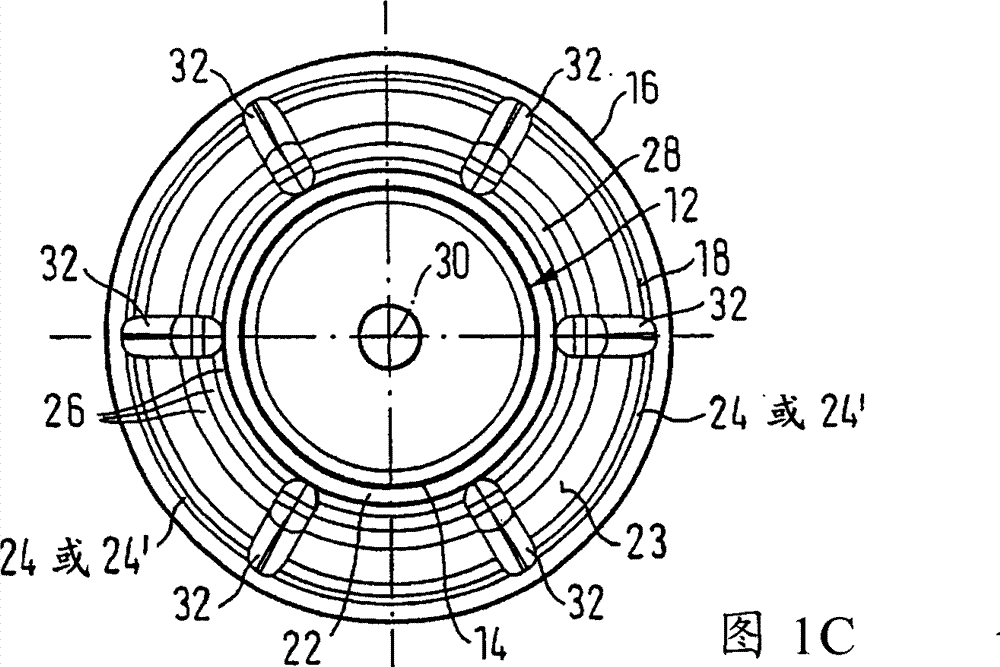
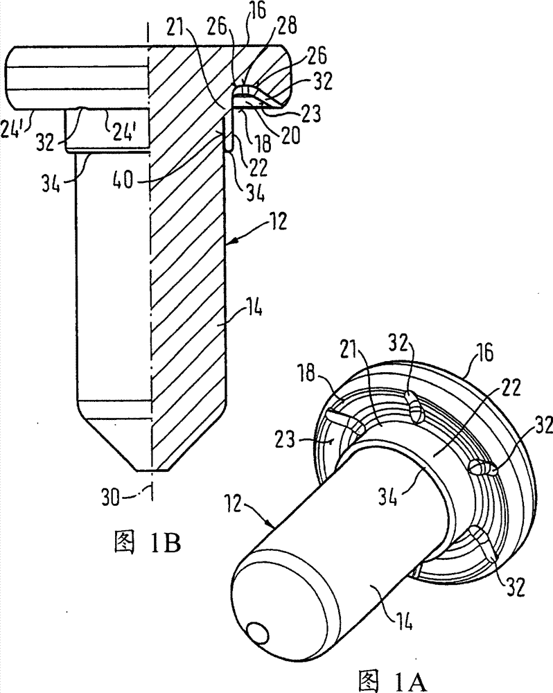
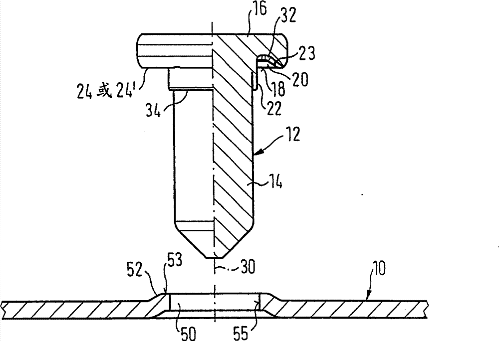
[0028] refer to Figures 1A-1C with Figure 2A-2B , shows the element 12 connected to the sheet metal part 10 by riveting. The element 12 is in the form of a centering element with a shank 14 and a head 16, wherein the head has on its side 18 facing the sheet metal part 10 an at least approximately annular groove 20 radially inside Merges with cylindrical section 21 of head 16 , which in turn merges with shank 14 and tubular riveting section 22 , which surrounds shank 14 in the region of head 16 , ie directly below head 16 . The annular groove 20 is located inside the annular contact surface 24, and the annular contact surface is located radially outside the annular groove, or is located radially outside the contact surface formed by the ring segment 24', and the annular groove 20 is located radially outside the annular groove. On the outside, the contact surface 24 or 24 ′ merges via an at least approximately conical wall 23 . The conical wall 23 may preferably have a con...


PUM


Abstract

The invention discloses an element which can be connected on the metal sheet component through riveting, particularly the element in the form of centering bolt. It consists of bar part and head part, among them the side facing metal sheet component of the head part is machined with circular groove or at least near-circular groove, the circular groove is apposed into the circular column section ofhead part in the radial inner side, and the circular column section is apposed into the bar part and the pipe-type riveting section, the riveting part circulates the bar part in the zone which head part in, the circular groove is located in the circular contact face which is arranged at the outer side of circular groove radically, and the circular groove is apposed on the circular contact face atthe radial outer side through the at least near conical wall, it is characterized by: the conical wall of circular groove and / or the circular bottom which is alternative on the circular groove are equipped with at least one local groove, preferentially several local groove particularly the local grooves distributed uniformly. The invention also discloses a piece unit which includes said elements and metal sheet component. It also discloses a method machining the piece unit.

Description

technical field [0001] The invention relates to an element connectable to a sheet metal part by riveting, in particular in the form of a centering bolt, which has a shank and a head, wherein the head has at least one An approximately ring-shaped annular groove which merges radially on the inside into a cylindrical section of the head which in turn merges into the shank and a tubular riveted section which encircles the shank in the region of the head , the annular groove is located in an annular contact surface arranged radially outside the annular groove and merges into the annular contact surface radially outside via an at least approximately conical wall. Furthermore, the invention relates to a component assembly comprising a sheet metal part connected to the element; and to a method of connecting the component to the sheet metal part. Background technique [0002] The element, component assembly and method referred to at the outset are known from FIGS. 8 and 9 of EP-A-0 ...

Claims


Application Information

Patent Timeline
Patent Type & Authority Patents(China)
IPC IPC(8): F16B35/06F16B5/02
Inventor 杰瑞·巴贝吉理查德·汉伯特迈克尔·维也斯
Owner PROFIL VERBINDUNGSTECHN
Why Eureka
Eureka Blog
Learn More