Connecting element, part assembly and method for forming the part assembly

A technology of components and parts, applied in the direction of connecting components, thin plate connections, mechanical equipment, etc., can solve the problems of deformation of riveted sections and inability to form riveted edges

Active Publication Date: 2014-07-16
PROFIL VERBINDUNGSTECHN
View PDF8 Cites 0 Cited by
  • Summary
  • Abstract
  • Description
  • Claims
  • Application Information

AI Technical Summary

Problems solved by technology

This proved to be practically difficult and it occurred that the sheet material was caught at the nose which provided the fixation against rotation, so that the riveted edge could not be formed and the riveted section deformed and was clamped approximately radially at the center pressed into sheet material

Method used


Image

  • Connecting element, part assembly and method for forming the part assembly
  • Connecting element, part assembly and method for forming the part assembly
  • Connecting element, part assembly and method for forming the part assembly

Examples


Embodiment Construction

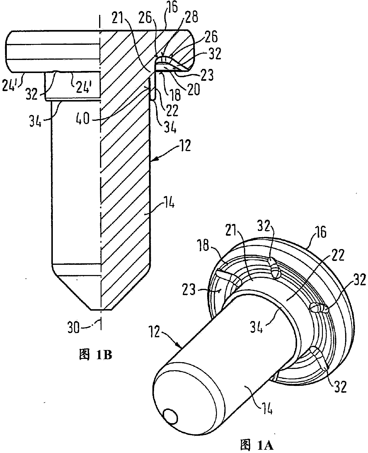
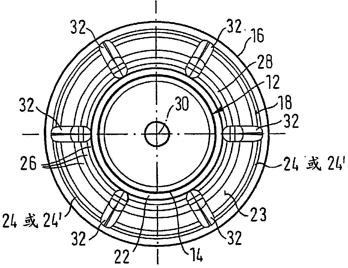
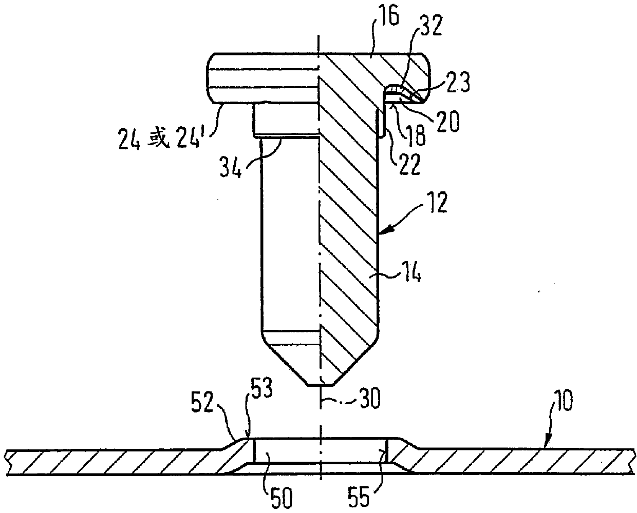
[0029] refer to Figures 1A-1C and Figure 2A-2B , shows the element 12 connected to the sheet metal part 10 by riveting. The element 12 is in the form of a centering element with a shank 14 and a head 16, wherein the head has on its side 18 facing the sheet metal part 10 an at least approximately annular groove 20 radially inside Merges with cylindrical section 21 of head 16 , which in turn merges with shank 14 and tubular riveting section 22 , which surrounds shank 14 in the region of head 16 , ie directly below head 16 . The annular groove 20 is located inside the annular contact surface 24, and the annular contact surface is located radially outside the annular groove, or is located radially outside the contact surface formed by the ring segment 24', and the annular groove 20 is located radially outside the annular groove. On the outside, the contact surface 24 or 24 ′ merges via an at least approximately conical wall 23 . The conical wall 23 may preferably have a cone...


PUM


Abstract

The invention discloses a connecting element, a part assembly and a method for forming the part assembly. The method for connecting an element to a metal sheet part so as to form the part assembly comprises the following steps of: inserting the element into the metal sheet part which is punched with a hole in advance, wherein the metal sheet part is pre-formed in an area with the holes so as to form a raised part, and the raised part is at least substantially matched with a recess in shape; forming a metal sheet material on the surrounding of a riveting section in the / each local recess by means of a leaf-shaped mold groove, wherein the leaf-shaped mold groove is provided with a central concave opening or a central hole and an annular raised part, the central concave opening or the central hole is used for receiving a rod part, and the central concave opening or the central hole is surrounded by the annular raised part; and putting or pressing the riveting section into the annular recess formed in the lower side surface of the metal sheet part in the forming process of a riveted edge.

Description

[0001] The application of the present invention is a divisional application of the invention application dated June 5, 2006, the application number is 200610083555.2, and the invention title is "elements and a component assembly that can be connected to sheet metal parts by riveting". technical field [0002] The invention relates to an element connectable to a sheet metal part by riveting, in particular in the form of a centering bolt, which has a shank and a head, wherein the head has at least one An approximately ring-shaped annular groove which merges radially on the inside into a cylindrical section of the head which in turn merges into the shank and a tubular riveted section which encircles the shank in the region of the head , the annular groove is located in an annular contact surface arranged radially outside the annular groove and merges into the annular contact surface radially outside via an at least approximately conical wall. Furthermore, the invention relates to...

Claims


Application Information

Patent Timeline
Patent Type & Authority Patents(China)
IPC IPC(8): F16B5/04F16B5/02
Inventor 杰瑞·巴贝吉理查德·汉伯特迈克尔·维也斯
Owner PROFIL VERBINDUNGSTECHN
Why Eureka
Try Eureka