Illuminating apparatus of light emitting diode

A technology for light-emitting diodes and lighting devices, which is applied to lighting devices, lighting device components, projection devices, etc., can solve problems such as affecting the projection quality of the projector 100 and increasing the complexity of the projector 100, thereby reducing the number and improving the stability. degree, the effect of increasing the lifespan

Inactive Publication Date: 2007-12-26
UNITED MICROELECTRONICS CORP
View PDF0 Cites 3 Cited by
  • Summary
  • Abstract
  • Description
  • Claims
  • Application Information

AI Technical Summary

Problems solved by technology

In addition, conventionally, the light source used in the lighting system of the projector 100 is an ultra-high pressure mercury lamp 101 in the form of a high-intensity discharge arc bulb. Since the light spectrum produced by this ultra-high pressure mercury lamp 101 is relatively weak in the red frequency band, the When designing the light splitting and synthesizing system, the ratio of red light, green light and blue light must be reconsidered in order to make the output image color balance, which increases the structural complexity of the entire projector 100. Therefore, there is an urgent need for a high spectrum purity and structure A simple lighting device replaces the ultra-high pressure mercury lamp 101 used in the conventional projector 100
Furthermore, since the lighting system of the conventional projector 100 adopts an ultra-high pressure mercury lamp 101, it is necessary to cooperate with the refracting mirror groups 115, 117, 119 and 121 and the dichroic mirror groups 131 and 133 in the light-combining system to combine the ultra-high pressure mercury lamps. The white light generated by the high-pressure mercury lamp 101 is separated into three primary colors of red, blue and green, and then combined by the light-combining prism 135 to output an image. Therefore, the optical path design of the projector 100 must be very precise. When the projector 100 is in the manufacturing process When the optical path is poorly assembled or affected by external mechanical forces such as vibration or transportation during operation, this complex optical path design is likely to be displaced or damaged due to a certain optical element, which will affect the projection quality of the projector 100; therefore, an improved one is urgently needed. The projector provides a simplified optical path structure, reduces the number of optical components in the conventional projector 100 to improve the reliability and stability of the projector 100 during operation

Method used


Image

  • Illuminating apparatus of light emitting diode
  • Illuminating apparatus of light emitting diode

Examples


Embodiment Construction

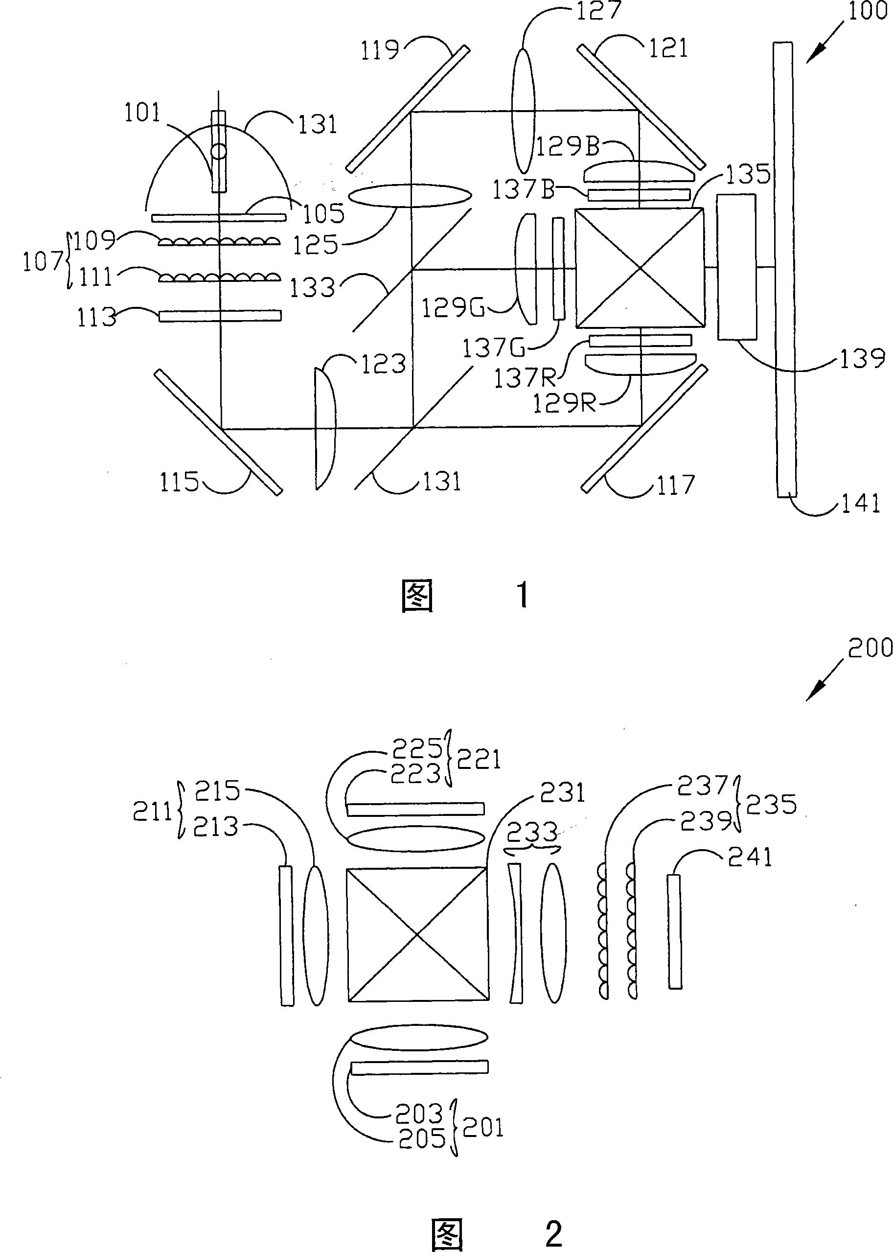
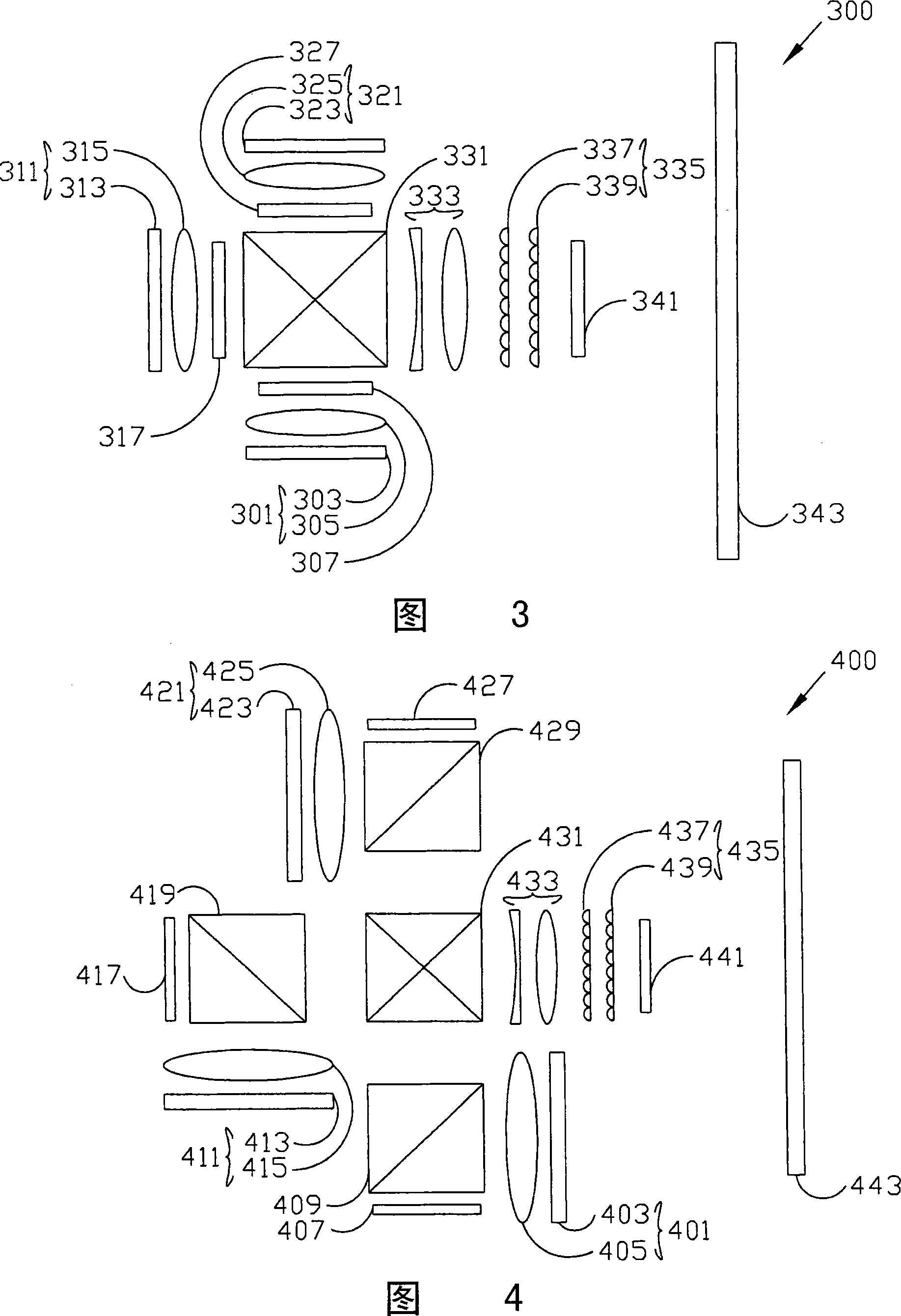
[0021] The following is a detailed description of the present invention, and the description of the LED lighting device and the projector using the LED lighting device in the following description does not include a complete structure. The prior art used in the present invention is only cited here with emphasis to help explain the present invention. Moreover, the relevant diagrams in the following texts are not drawn according to the actual scale, and their function is only to express the structural features of the present invention.

[0022] The invention provides a light-emitting diode lighting device, which uses red, green and blue monochromatic light-emitting diode arrays to form a three-sided light-emitting diode panel as the light source of the projector, which can prevent other optical elements in the projector from being damaged by heat radiation, and further Reduce the maintenance cost of the projector; in addition, the projector using the light-emitting diode lightin...


PUM


Abstract

This invention provides a LED illumination device used in projectors, which takes three spectrums of red, green and blue monochromatic irradiance diode arrays to form a diode panel emitting light from three sides as the light source of the projector, then uses a synthesized prism to merge them to a beam generated by the three LED panels and outputs images with a lens component, which not only can solve the problem that a super high voltage Hg lamp used in a traditional projector generates thermo-radiation and harms the machine and other optical elements but also can simplify the complicated optical system.

Description

[0001] This application is a divisional application with a filing date of October 22, 2003 and an application number of 200310102865.0. (1) Technical field [0002] The present invention relates to an illuminating device, in particular to an LED illuminating device used in a projector as a light source. (2) Background technology [0003] With the prevalence of multimedia presentations, the projector has become one of the necessary computer equipment in the office. Quantization, high image quality, low noise and long light source life to meet the convenience and needs of popular use. [0004] FIG. 1 is a schematic diagram of the structure and optical path of a conventional projector 100 . Its structure is mainly composed of an illumination system, a light separation and synthesis system and an imaging system. The lighting system includes an ultra-high pressure mercury lamp (UHP mercury lamp, Ultra High Pressure mercury lamp) 101, a parabolic reflector (reflector) 103, an ul...

Claims


Application Information

Patent Timeline
Patent Type & Authority Applications(China)
IPC IPC(8): F21V5/02F21V5/04F21V9/08G03B21/20F21Y101/02F21Y113/00F21Y113/13F21Y115/10
Inventor 姜柏良刘怡纬
Owner UNITED MICROELECTRONICS CORP
Why Eureka
Try Eureka