Shunt opening release capable of being controlled by external electricity-breaking protection signal

A shunt release, signal control technology, applied in the direction of automatic disconnection of emergency protection devices, protections that respond to undervoltage or no voltage, emergency protection circuit devices, etc. The state cannot be known, the coil is easy to burn, etc., to achieve the effect of expanding the application field

Inactive Publication Date: 2008-01-09
万家盛
View PDF0 Cites 5 Cited by
  • Summary
  • Abstract
  • Description
  • Claims
  • Application Information

AI Technical Summary

Problems solved by technology

However, when it is necessary to disconnect the air switch in time in other situations, it cannot be realized.
In the event of a fire, it is generally necessary to manually cut off the power supply after the firefighters arrive at the scene.
For another example, in the process of power management, if someone illegally loosens the electronic seal of the meter box, the release cannot make the circuit breaker disconnect the circuit in time; It only acts when the current between the phase lines is unbalanced, and does not act in other cases. Therefore, the use of various circuit breakers with this kind of shunt release is greatly limited.
In addition, for this kind of circuit breaker with shunt release, after the circuit breaker

Method used


Image

  • Shunt opening release capable of being controlled by external electricity-breaking protection signal
  • Shunt opening release capable of being controlled by external electricity-breaking protection signal
  • Shunt opening release capable of being controlled by external electricity-breaking protection signal

Examples


Embodiment Construction

[0024] The present invention will be further described below in conjunction with accompanying drawing:

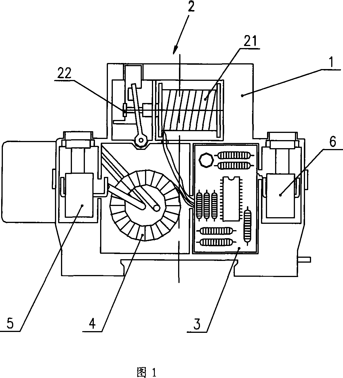
[0025] Please refer to FIG. 1 , which is a schematic view of the mechanical structure of an embodiment of the present invention. The shunt release includes a housing 1, an electromagnet 2 composed of a coil 21, an armature 22, etc., a control circuit 3, a current transformer 4, a power terminal 5 and a signal input terminal 6 are arranged in the housing 1 , from which the signal input terminal 6 can be connected to external equipment control signals. The current transformer 4 is set on the phase line L and the neutral line N, and is electrically connected with the control circuit 3, the coil 21, the power terminal 5 and the signal input terminal 6, and the signal input terminal 6 is used to communicate with the external The device that generates the power-off protection signal is connected.

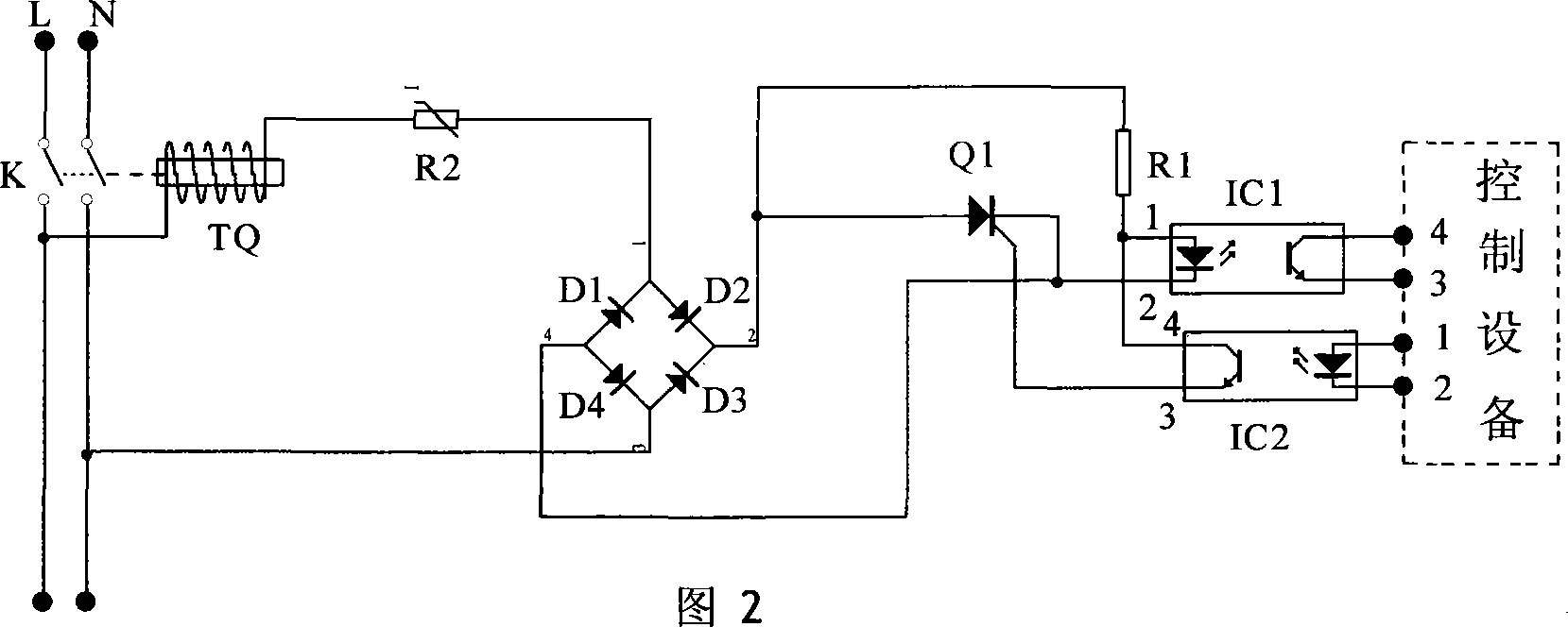
[0026] Please refer to FIG. 2 . FIG. 2 is a schematic structural diagram of a co...


PUM


Abstract

The invention is concerned with the exterior electric-short protective signal controlled shunt release, includes: the shell 1, which contents the electromagnet2 with the coil21 and the armature22, the control circuit3, the current transformer4, the power supply wiring pole5 and the signal receiving wiring pole5. The control circuit3's switch control circuit includes the integrated circuit IC2, the resistance R2, the controllable silicon Q1, the bridge reactor D1 - D4, and the electromagnet, it is: the 1, 2 foot of the IC2 receive the exterior signal and connect the 3, 4 foot that control the connection of the Q1 and active the electromagnet TQ for driving the linkage machine off the switch K; the operating state of the switch indicates the circuit includes the R1 and the integrated circuit 1, which cuts off the connection of the 3, 4 foot of the IC1 and with no current passes though the 1, 2 foot of the IC1, and no voltage outputs from the bridge reactor D1-D4. The invention is unlikely burns the tripping coils with high frequency movement and with one or more than one exterior signals control the breaker switch.

Description

[0001] Explanation: The switch in this article is equal to the circuit breaker, and the air switch is a kind of circuit breaker. technical field [0002] The invention relates to a low-voltage electric appliance product, in particular to a shunt tripper used in combination with a circuit breaker. Background technique [0003] Existing shunt trippers equipped with circuit breakers, such as shunt trippers matched with leakage protection switches, also known as air switches, generally include a casing, and a device composed of a coil and an armature is arranged in the casing. Tripping mechanism, mutual induction coil, control circuit and terminal, etc. The mutual induction coil is set on the phase line and the neutral line. When the current on the phase line and the neutral line changes, the mutual induction coil will generate a current, which is input into the control circuit, and the thyristor in the control circuit is turned on. A loop is formed between the neutral line and...

Claims


Application Information

Patent Timeline
IPC IPC(8): H01H83/12H01H71/04H01H83/14H02H3/24H02H3/04H02H3/32
Inventor 万家盛汪志强
Owner 万家盛
Why Eureka
Try Eureka