

Light guiding member and light guiding plate using the same
A technology of light guide and light guide plate, applied in the field of light guide plate
Active Publication Date: 2010-11-24
LITE ON OPTO TECH (CHANGZHOU) CO LTD +1
View PDF0 Cites 0 Cited by
- Summary
- Abstract
- Description
- Claims
- Application Information
AI Technical Summary
Problems solved by technology
In addition, the side part of the package in the non-light-emitting area may also leak light to reduce the amount of light received by the light-incident surface R1
Method used
View moreImage
Smart ImageViewing Examples


Examples
no. 1 example
no. 2 example
no. 3 example
Login to View More PUM
| Property | Measurement | Unit |
|---|---|---|
| angle | aaaaa | aaaaa |
Abstract
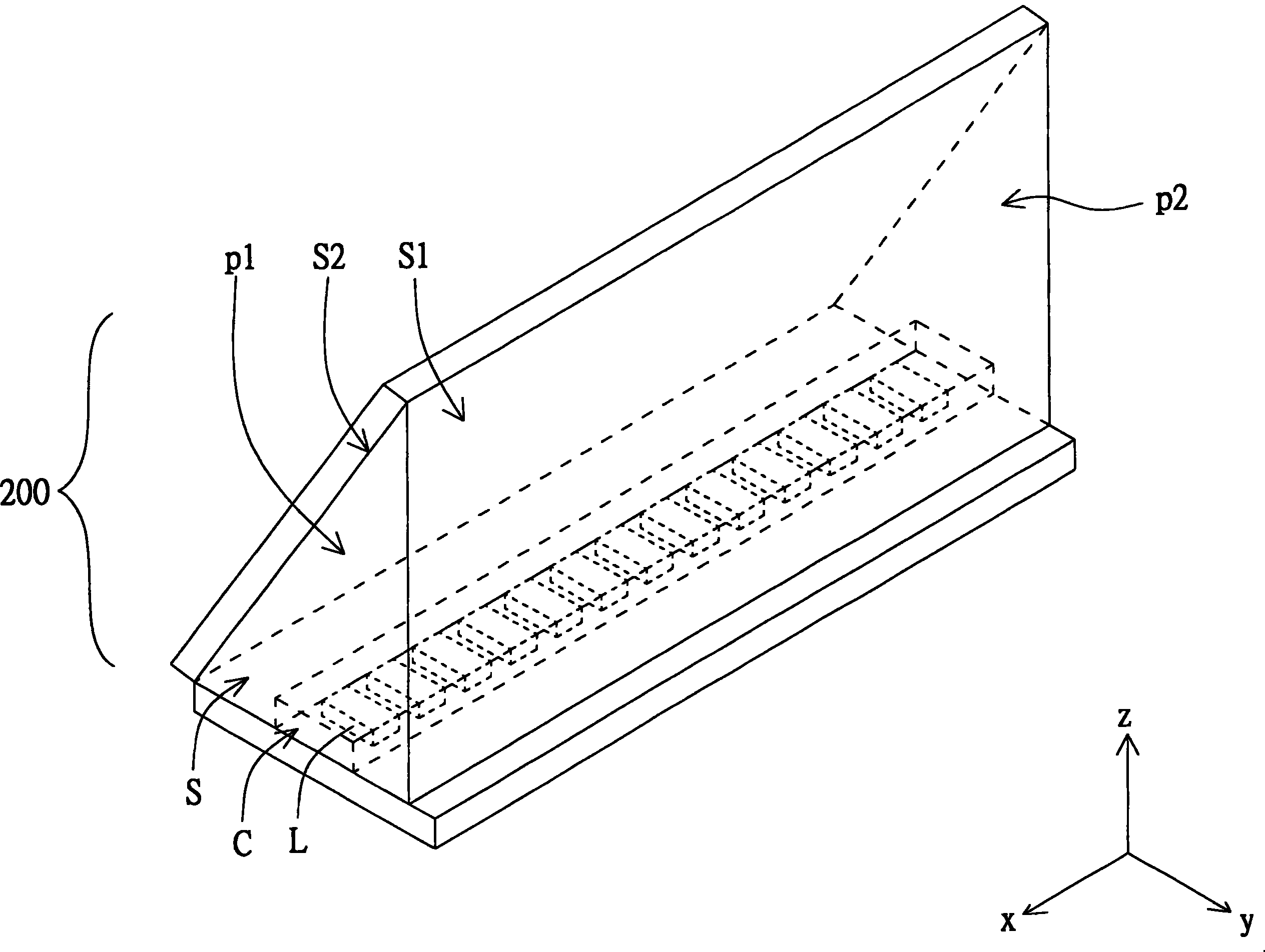
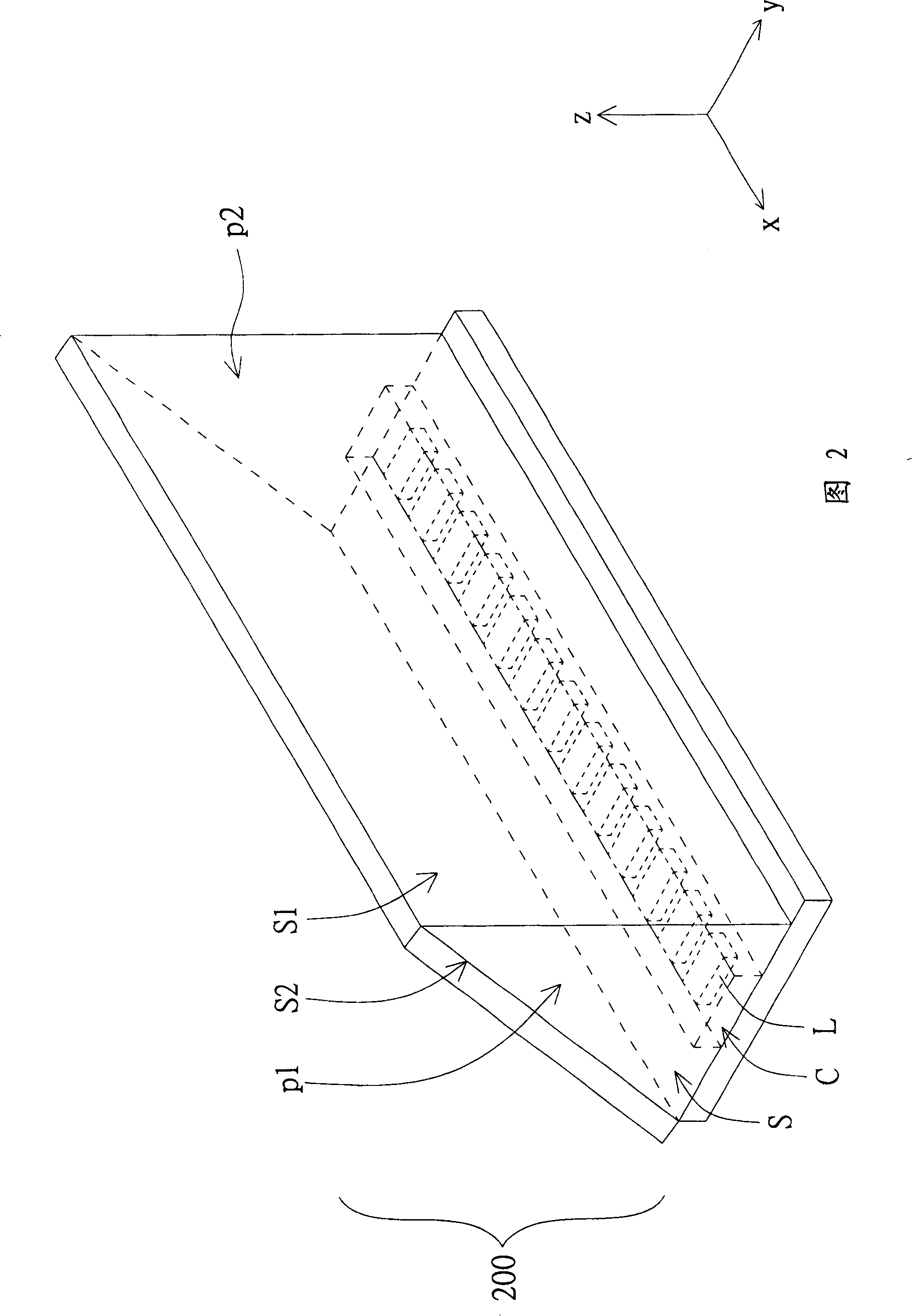
The present invention discloses a light-conducting piece which is provided with a first surface, a second surface and a bottom surface. The bottom surface, the first surface and the second surface limit the inner side of the light-conducting piece. The bottom surface is provided with a groove in order that light emits from the inner side of the light-conducting piece via the first surface when the light source lies in the groove and produces light.
Description
Light guide and light guide plate using the light guide technical field The invention relates to the field of light guide technology, in particular to a light guide member capable of increasing light utilization and a light guide plate using the same. Background technique Please refer to FIG. 1 , which shows a partial structure diagram of a conventional backlight module. The backlight module 100 is, for example, an edge-lit backlight module, and includes a light source 110 and a light guide plate 120 . The light guide plate 120 is generally a wedge-shaped plate or a flat plate, and has a light incident surface R1 and a light exit surface R2. The light source 110 is, for example, a light emitting diode (Light Emitting Diode, LED) light bar, and is disposed adjacent to the light incident surface R1. The light source 110 is used to generate light, and enter the light guide plate 120 through the light incident surface R1 , and then guide the light to the light exit surface R...
Claims
Login to View More Application Information
Patent Timeline
 Patent Type & Authority Patents(China)
IPC IPC(8): G02B6/00G02B1/04G02B6/122
Inventor 刘育男王慈维
Owner LITE ON OPTO TECH (CHANGZHOU) CO LTD