Light guiding member and light guiding plate using the same

A technology of light guide and light guide plate, applied in the field of light guide

Active Publication Date: 2008-04-02
LITE ON OPTO TECH (CHANGZHOU) CO LTD +1
View PDF0 Cites 3 Cited by
  • Summary
  • Abstract
  • Description
  • Claims
  • Application Information

AI Technical Summary

Problems solved by technology

In addition, the side part of the package in the non-light-emitting area may also leak light to reduce the amount of light received by the light-incident surface R1

Method used


Image

  • Light guiding member and light guiding plate using the same
  • Light guiding member and light guiding plate using the same
  • Light guiding member and light guiding plate using the same

Examples


no. 1 example

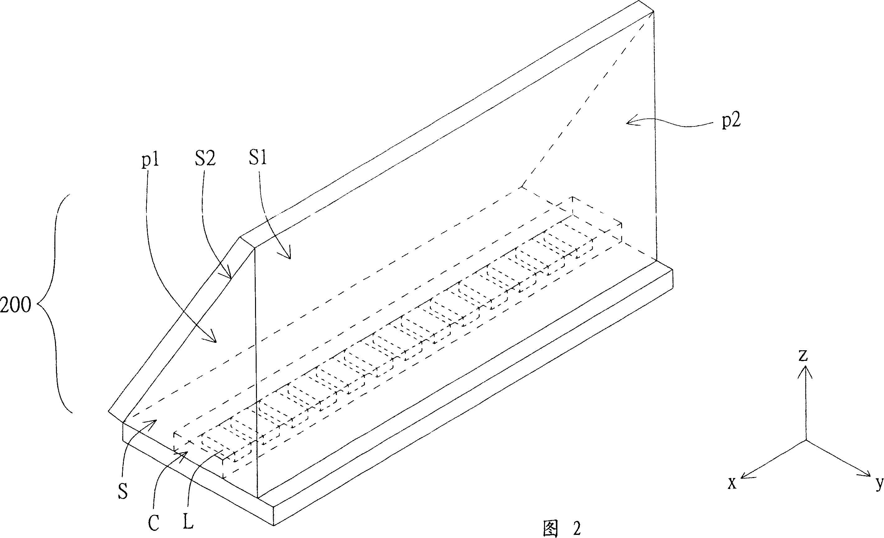
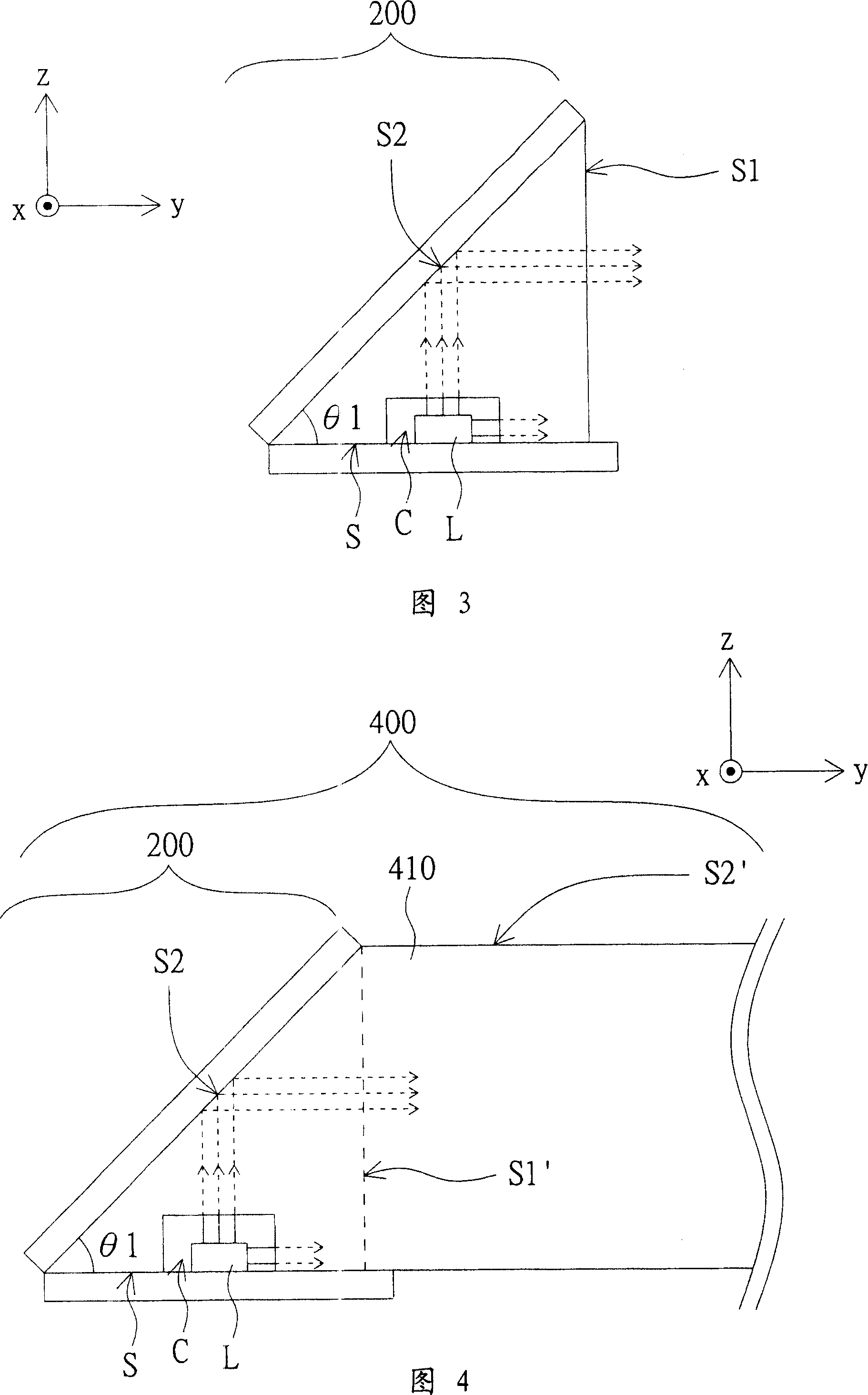
[0030] Please refer to FIG. 2, which illustrates a schematic diagram of the light guide according to the first embodiment of the present invention when a light source is embedded. In the first embodiment, the light guide 200 is substantially a column (a triangular column as shown in FIG. 2), and has a first surface S1 (parallel xz plane), a second surface S2, and a bottom surface S (parallel xy plane). ) And the two side faces p1 and p2 (parallel yz plane) intersecting the above three faces. The first surface S1, the second surface S2, and the bottom surface S are adjacent to each other in pairs, and jointly define the interior of the light guide 200, that is, the volume range surrounded by the three surfaces.

[0031] In addition, the bottom surface S has a groove C for accommodating the light source L. In the first embodiment, the light source L is a light emitting diode (Light Emitting Diode, LED) group as an example for illustration, that is, LED packages arranged side by side...

no. 2 example

[0035] Please refer to FIG. 5, which illustrates a side view of the light guide according to the second embodiment of the present invention when a light source is embedded. The second embodiment is different from the first embodiment in that the second surface T2 of the light guide 500 further has a V-cut structure. And preferably, the cut surface of each V-shaped groove is 45 degrees with the bottom surface. As a result, the second surface T2 achieves the same reflection effect as the first embodiment with the cut surface of the groove, and the acute angle θ2 between the second surface T2 and the bottom surface T can have greater adjustment flexibility. For example, θ2 can be 30 degrees. The height of the first surface T1 is smaller than the first surface S1 of FIG. 3. When applied to the light guide plate, the thickness of the body of the light guide plate can be effectively reduced, making the backlight module and the display lighter and thinner.

no. 3 example

[0037] Please refer to FIG. 6, which illustrates a side view of the light guide according to the third embodiment of the present invention when a light source is embedded. In the third embodiment, the second surface U2 of the light guide 600 is an arc surface. The curvature of the arc can also be adjusted depending on the type of light source L or the preset height of the first surface U1, for example, it is a part of an arc or a cast surface. Fig. 6 takes the arc as an example. Of course, a suitable V-shaped prism structure can also be added to part of the second surface U2 as in the second embodiment.


PUM

PropertyMeasurementUnit
angleaaaaaaaaaa

Abstract

The present invention discloses a light-conducting piece which is provided with a first surface, a second surface and a bottom surface. The bottom surface, the first surface and the second surface limit the inner side of the light-conducting piece. The bottom surface is provided with a groove in order that light emits from the inner side of the light-conducting piece via the first surface when the light source lies in the groove and produces light.

Description

Technical field [0001] The present invention relates to the technical field of light guide, in particular to a light guide that can increase the light usage rate and a light guide plate using the same. Background technique [0002] Please refer to FIG. 1, which shows a partial structural diagram of a conventional backlight module. The backlight module 100 is, for example, an edge type backlight module, and includes a light source 110 and a light guide plate 120. The light guide plate 120 is generally a wedge-shaped plate or a flat plate, and has a light incident surface R1 and a light output surface R2. The light source 110 is, for example, a light emitting diode (Light Emitting Diode, LED) light bar, and is disposed at a position adjacent to the light incident surface R1. The light source 110 is used to generate light and enter the light guide plate 120 through the light incident surface R1, and then guide the light through the light guide plate 120 to the light exit surface R2 ...

Claims


Application Information

Patent Timeline
Patent Type & Authority Applications(China)
IPC IPC(8): G02B6/00G02B1/04G02B6/122
Inventor 刘育男王慈维
Owner LITE ON OPTO TECH (CHANGZHOU) CO LTD
Why Eureka
Try Eureka