Variable valve lift follower for vehicle

A valve lift, variable technology, applied in the direction of engine components, engine control, machine/engine, etc., can solve the problems of increasing the inertial mass of valve movement and affecting the dynamic performance of valve mechanism, etc.

Inactive Publication Date: 2008-04-16
HYUNDAI MOTOR CO LTD
View PDF1 Cites 18 Cited by
  • Summary
  • Abstract
  • Description
  • Claims
  • Application Information

AI Technical Summary

Problems solved by technology

Therefore, the effective mass of the follower increases the inertial mass of the valve motion, thus affecting the dynamic performance of the valve train

Method used


Image

  • Variable valve lift follower for vehicle
  • Variable valve lift follower for vehicle
  • Variable valve lift follower for vehicle

Examples


Embodiment Construction

[0019] Next, preferred embodiments of the present invention will be described in detail with reference to the accompanying drawings.

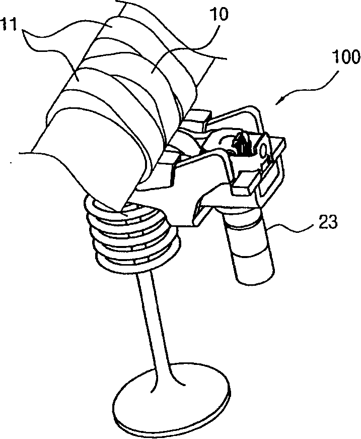
[0020] In some embodiments, the variable valve lift follower includes three cams for each valve, and the opening amount of the valve is controlled by the rotational force of the cam device according to the engine state. A middle-low lift cam 10 and two high-lift cams 11 are arranged in a row.

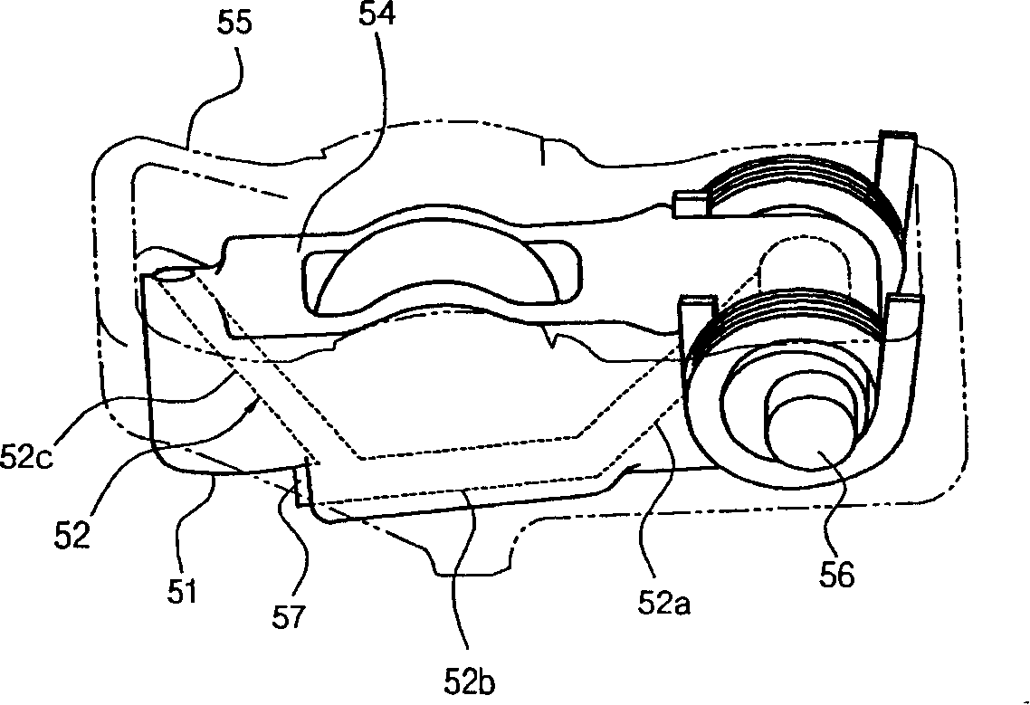
[0021] The ejector pin formed on the top of the valve contact portion 51 arranged opposite to the HLA 23 moves in the longitudinal direction to connect the inner body 54 and the outer body 55 to each other, thereby generating a high lift there.

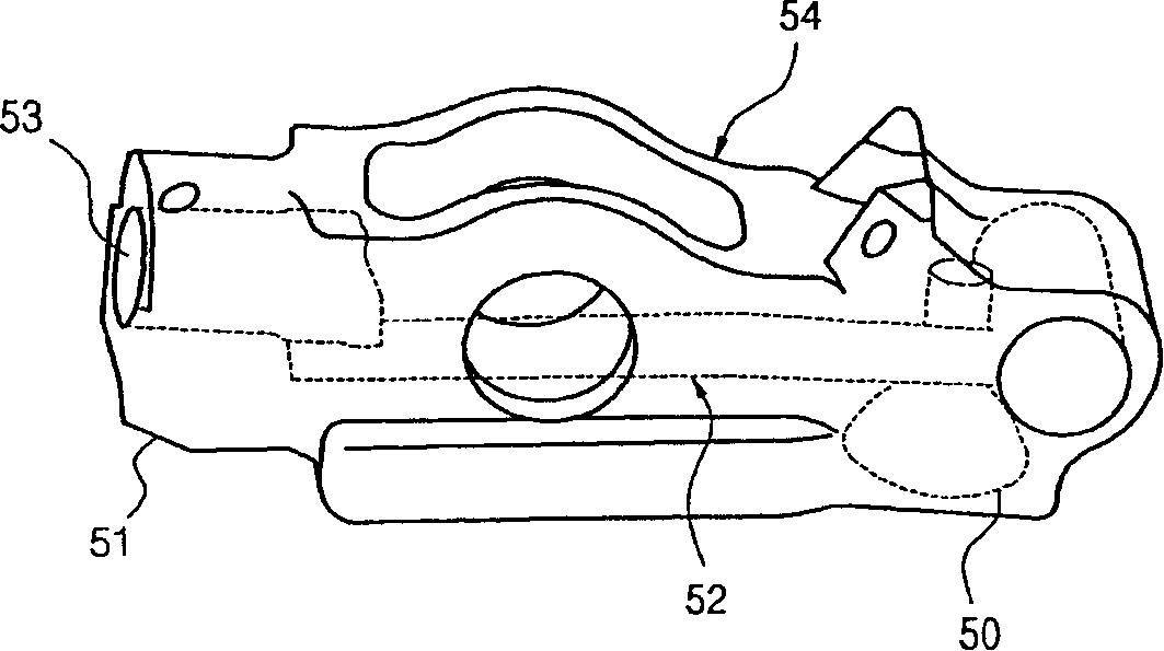
[0022] The HLA contact portion 50 for supplying oil to the inner body 54 is arranged at the bottom of one side of the inner body 54 , the valve contact portion 51 is arranged at the bottom of the other side of the inner body 54 , and the ejector pin is arranged at the top of the valve contact portion 51 .

[00...


PUM


Abstract

A variable valve lift follower for a vehicle includes an outer body receiving a rotational force from a high lift cam; an inner body with a first end portion hinge-connected with the outer body, receiving a rotational force from a low lift cam; a hydraulic lash adjuster (HLA) contact portion for supplying oil to the first end portion of the inner body; a valve contact portion on a second end of the inner body; and a knock pin on the top of the valve contact portion, connecting the outer body to the inner body during high lift.

Description

[0001] Cross References to Related Applications [0002] This application is based on and claims priority from Korean Application No. 10-2006-0098272 filed on October 10, 2006, the entire disclosure of which is incorporated herein by reference. technical field [0003] The invention relates to a variable valve lift follower of a vehicle, more particularly to a variable valve lift follower of a vehicle with a push pin on the valve contact portion. Background technique [0004] Typically, the airflow in the engine varies considerably as the speed of the internal combustion engine varies between 500 rpm and 6,000 rpm. In a reciprocating internal combustion engine that controls the flow of air and exhaust gas by opening and closing the intake valve and exhaust valve, in order to obtain greater power at high speeds, it is necessary to increase the charging efficiency by lengthening the opening time of the intake valve, which makes The overlap with the exhaust valve becomes large...

Claims


Application Information

Patent Timeline
Patent Type & Authority Applications(China)
IPC IPC(8): F01L13/00F02D13/02
CPCF01L1/2405F01L2820/01F01L1/185F01L2105/00F01L13/0036F01L2001/186F01L2305/00F01L1/18F01L1/14F01L13/00
Inventor 吴廷翰
Owner HYUNDAI MOTOR CO LTD
Why Eureka
Try Eureka