
Residual current operated circuit breaker

A residual current and circuit breaker technology, applied in the field of residual current operated circuit breakers

Active Publication Date: 2008-04-30
GEWISS SPA
View PDF0 Cites 0 Cited by
  • Summary
  • Abstract
  • Description
  • Claims
  • Application Information

AI Technical Summary

Problems solved by technology

[0008] However, it is well known that this test is not always performed for reasons of inadvertence and because of the inconvenience caused by power interruptions

Method used


Image

  • Residual current operated circuit breaker
  • Residual current operated circuit breaker
  • Residual current operated circuit breaker

Examples


Embodiment Construction

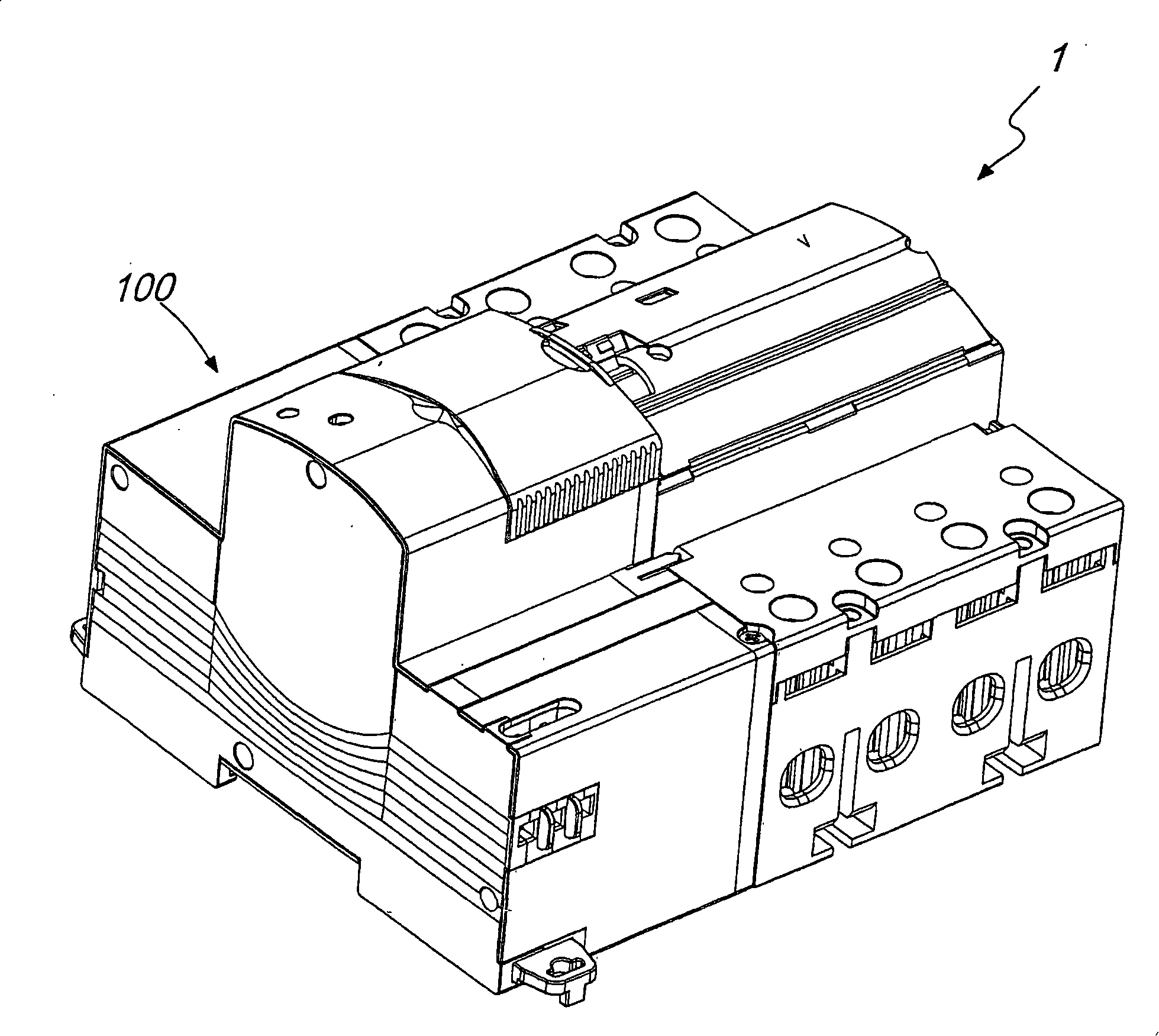
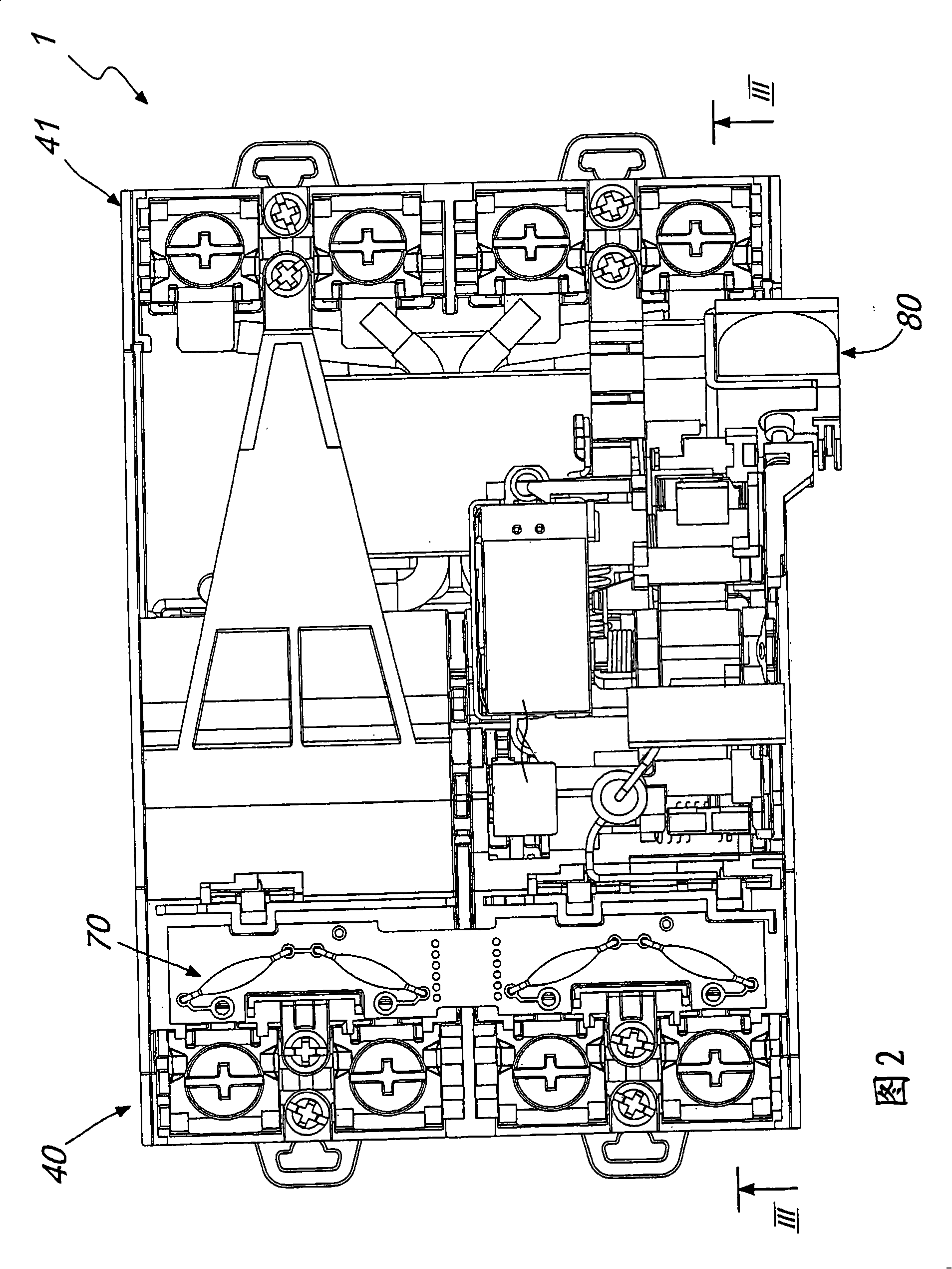
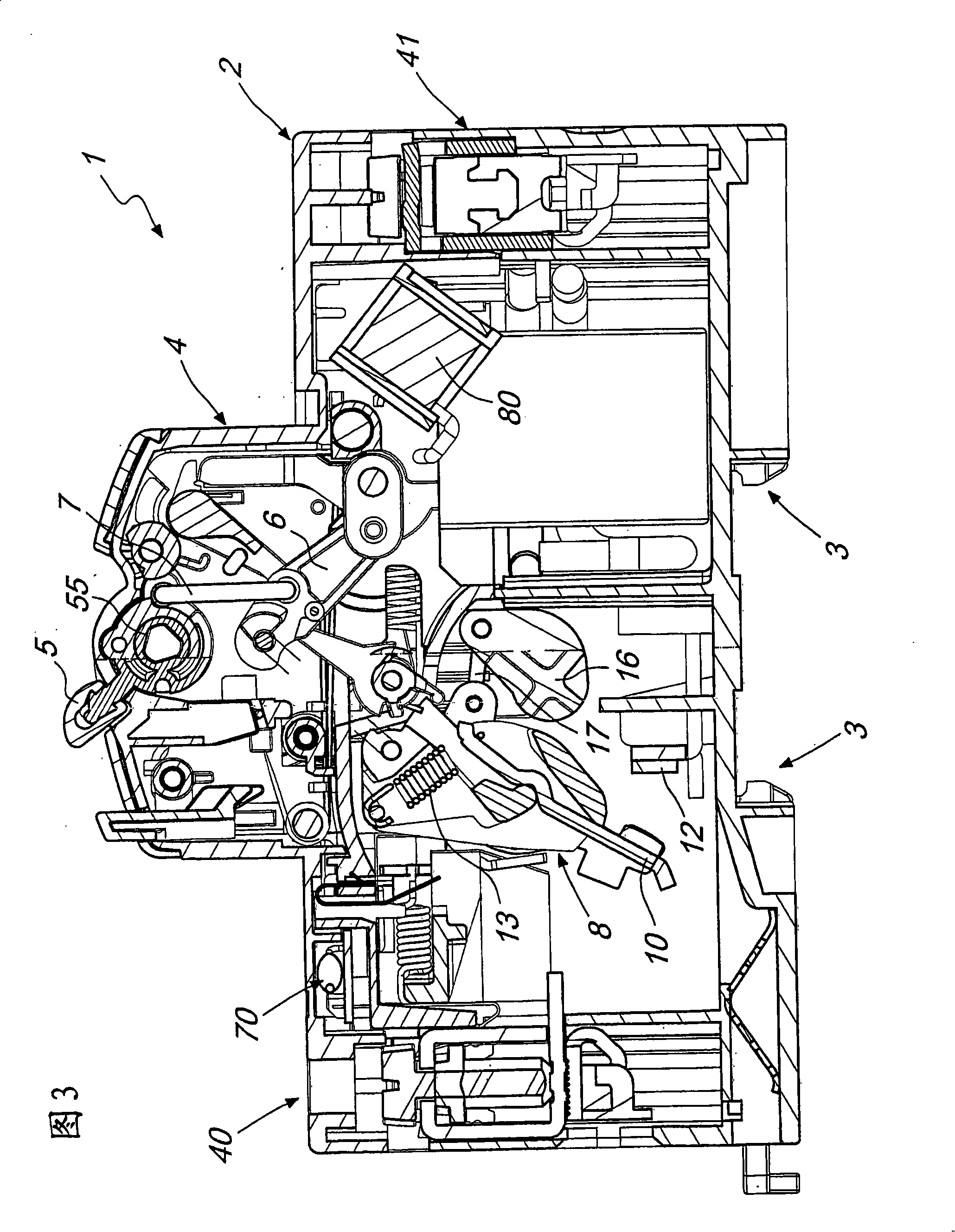
[0038] With reference to these cited figures, a residual current operated circuit breaker according to the invention and generally designated by reference numeral 1 comprises a box-shaped body 2 having typical standard shape.

[0039] The body 2 has on its front a protrusion 4 in which is arranged an actuating device of the type known in the prior art, comprising a handle 5 adapted to actuate the mechanism for actuating the contacts.

[0040] The handle 5 is rigidly connected to the rotor 55 .

[0041] The actuation mechanism comprises a motor rod 6 connected by means of a cross member 7 to a rotor 55 of the handle, which acts on a contact support 8 by means of a rod 9 .

[0042] The contact support 8 is adapted to support two separate sets of contacts: a set of main contacts 10 and a set of secondary or auxiliary contacts 11 .

[0043] In a specific case, there are four main contacts 10 and four corresponding secondary contacts 11 .

[0044] The main contact 10 and the sec...


PUM


Abstract

A residual current operated circuit breaker 1 comprising a first terminal strip 40 and a second terminal strip 41, that are associated respectively with moving contacts 10, 11 and fixed contacts 12, a control relay 30 suitable to act on the mechanism for opening the moving contacts, in case of tripping. The moving contacts comprise two separate series of contacts, a series of main contacts 10 and a series of secondary or auxiliary contacts 11, that are supported on a single contact supporting member 8 and can move independently so as to allow the flow of current between the first and second terminal strips when the main contacts 10 are open, by means of the auxiliary contacts 11.

Description

technical field [0001] The invention relates to a residual current operated circuit breaker. Background technique [0002] As is well known, residual current operated circuit breakers are usually provided in household systems and industrial systems to prevent fault current from causing danger to users and loads connected to the wires. [0003] Essentially, when the presence of a fault current is detected, the residual current circuit breaker opens the line, thereby interrupting the power supply to the loads arranged downstream. [0004] After the residual current circuit breaker has been opened, the residual current circuit breaker must be reset once the system has returned to correct operating conditions. [0005] Since the fault is an overvoltage induced transient type, this operating condition usually recovers spontaneously. [0006] This reset is usually done manually by acting on a suitably positioned reset lever. [0007] Furthermore, known types of residual current...

Claims


Application Information

Patent Timeline
IPC IPC(8): H01H71/00H01H71/10H01H83/14
CPCH01H83/04
Inventor D·伯萨特里S·皮亚内佐拉A·康塔尔迪
Owner GEWISS SPA
Learn More