LED lamps

A technology of LED lamps and bearing surfaces, applied in the field of LED lighting, can solve the problems of small light-emitting angle and the like

Inactive Publication Date: 2008-05-21
NINGBO YAMAO OPTOELECTRONICS CO LTD
View PDF0 Cites 14 Cited by
  • Summary
  • Abstract
  • Description
  • Claims
  • Application Information

AI Technical Summary

Problems solved by technology

In the existing LED lamps, the LED components are placed on a flat circuit board. This kind of device

Method used


Image

  • LED lamps
  • LED lamps
  • LED lamps

Examples


Embodiment 1

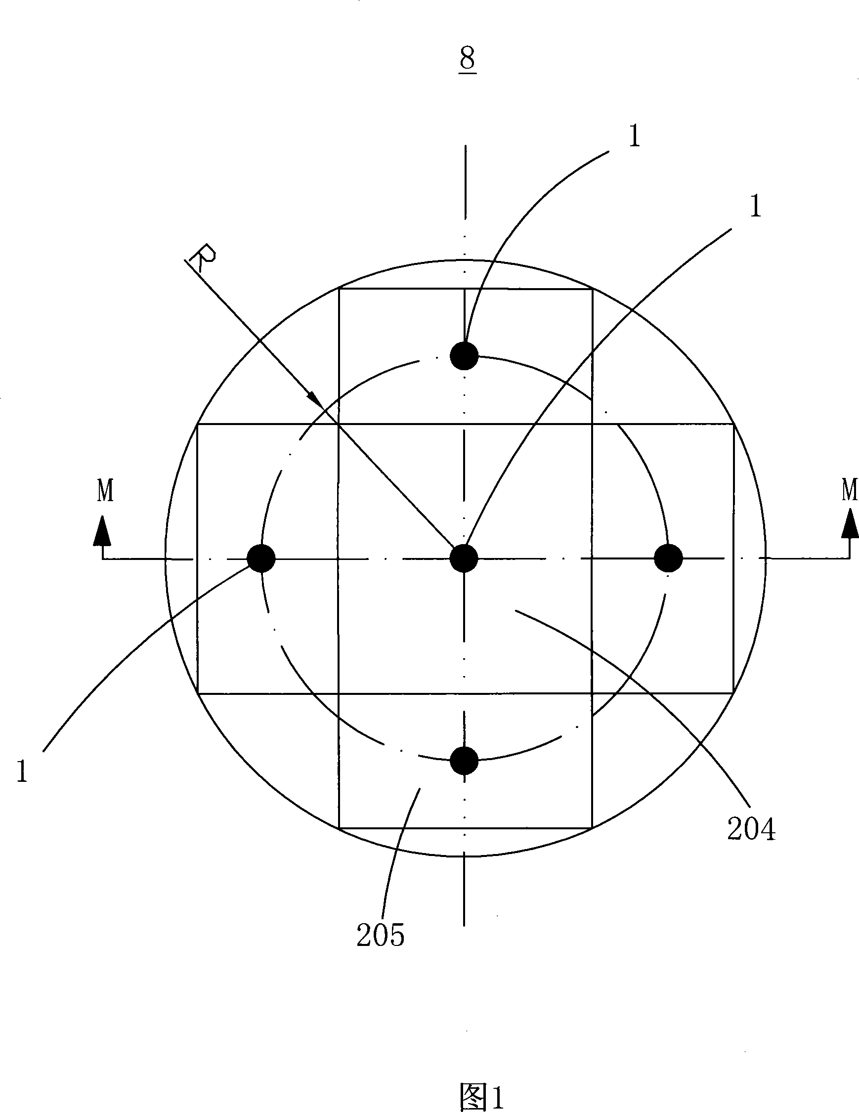
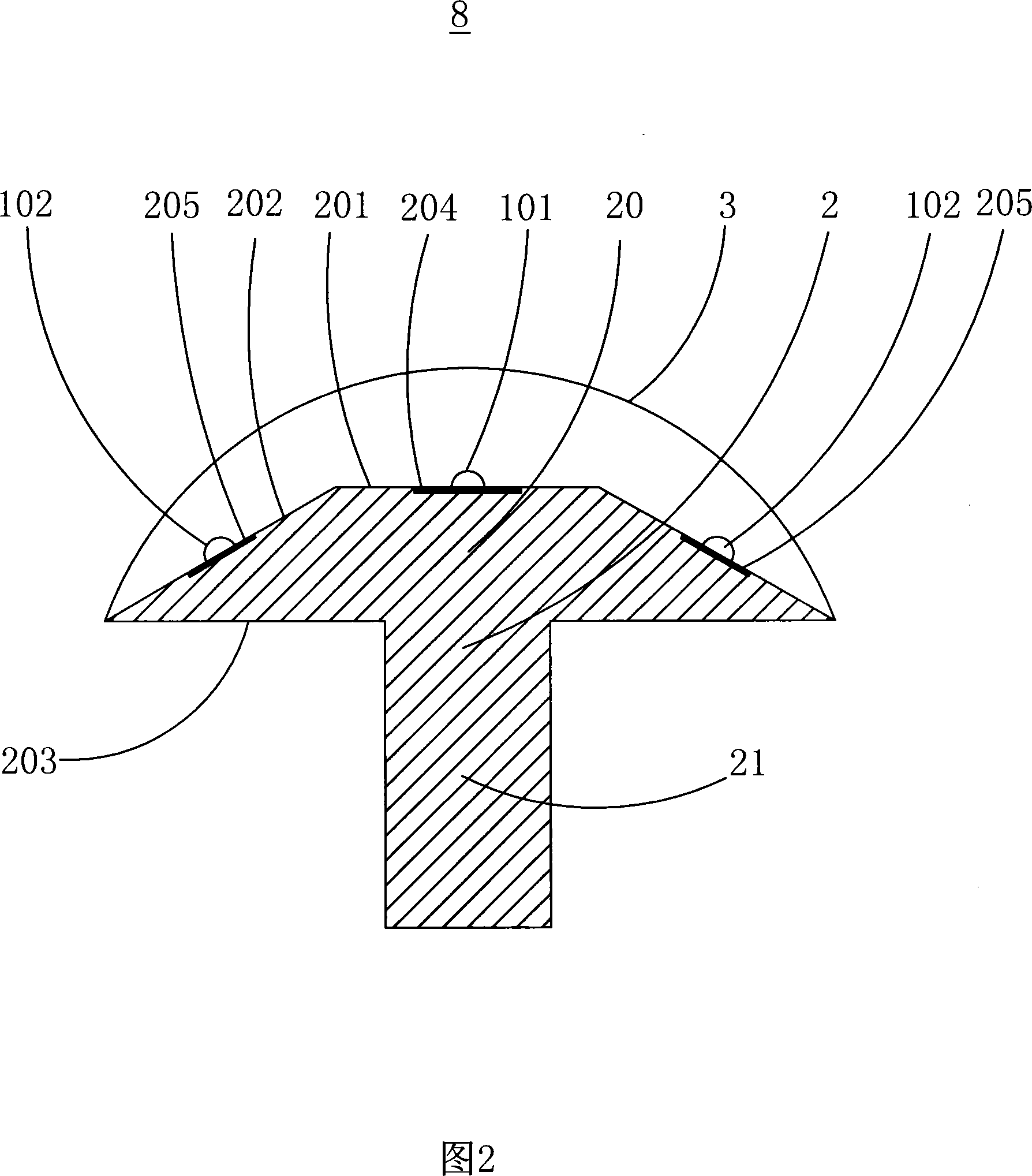
[0024] Please refer to Fig. 1 and Fig. 2, the LED lamp 8 disclosed in this embodiment includes an LED 1, an LED carrier 2 and a lens 3, wherein the LED 1 is a high-power LED, and the LED carrier 2 includes a carrier The base 20 and the heat dissipation portion 21, the carrying base 20 and the heat dissipation portion 21 are both made of a material with good thermal conductivity (such as aluminum), and the carrying base 20 and the heat dissipation portion 21 are integrally formed, of course, they can also be formed separately, Then connect with heat conduction. In this embodiment, the LED carrying base 20 is in the shape of a circular truncated cone, and is composed of an upper end surface 201, a side surface 202, and a lower end surface 203, wherein the upper end surface 201 of the LED carrying base 20 forms a first LED 101 bearing. LED bearing surface 204 (in this embodiment, bearing surface 204 is a part of upper end surface 201, certainly, bearing surface 204 can also be th...

Embodiment 2

[0027] The difference between the LED lamp 8' disclosed in this embodiment and the LED lamp 8 disclosed in Embodiment 1 is that the carrying base is polygonal.

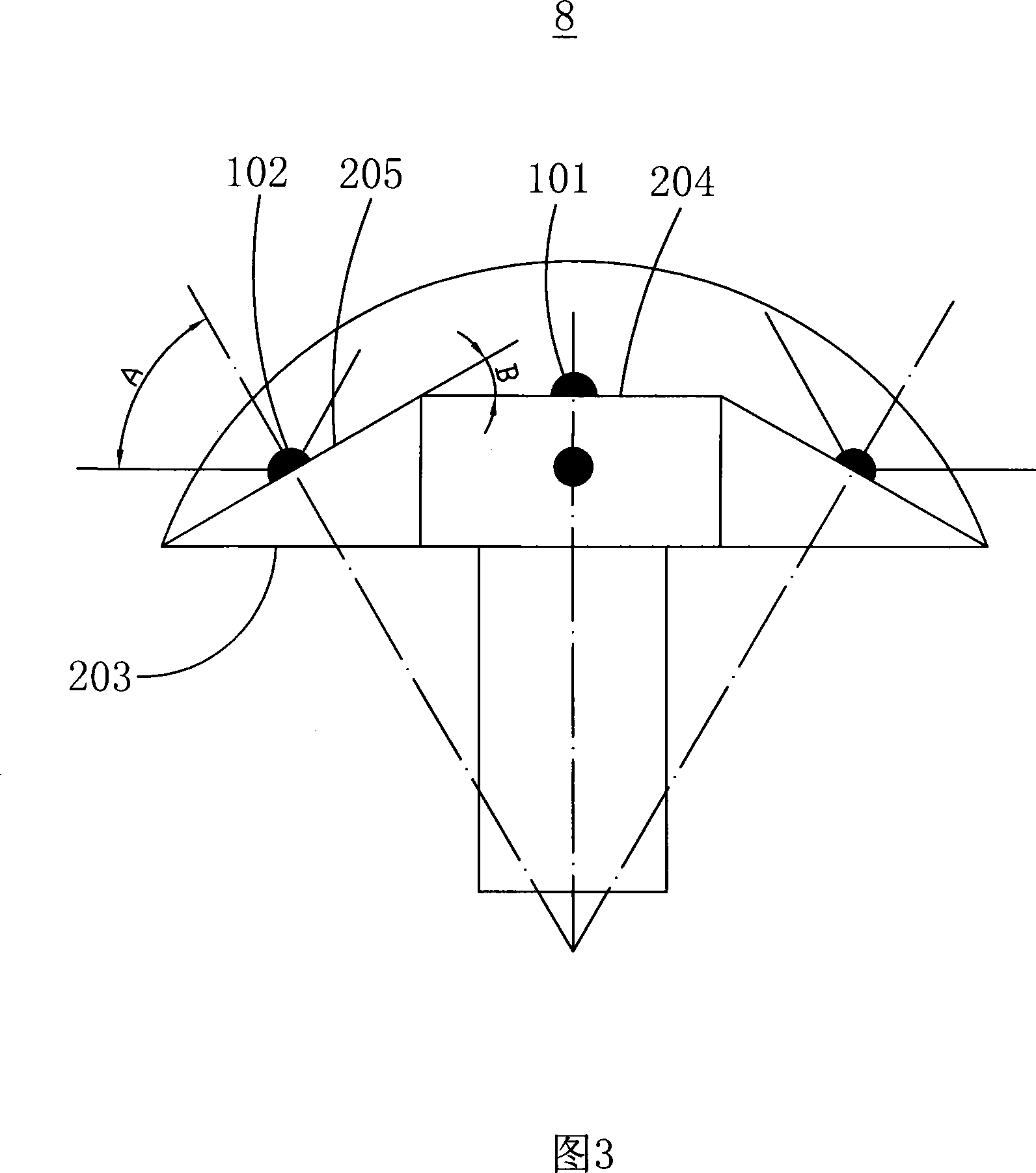
[0028] Please refer to Fig. 4 and Fig. 5, the bearing base 20' is in the shape of a hexagonal truss. The second LED bearing surface 205' is the side surface of the hexagonal truss, a first LED bearing surface 204' is formed on the upper end surface (not numbered) of the hexagonal truss, and the first LED 101' is arranged on the The center of the first LED bearing surface 204', the half-angle of light emission of the second LED 102' on the second LED bearing surface 205' is A', the first LED bearing surface 204' and the second bearing surface 205 The included angle between 'is B', and the size of the light emitting half-angle A' and the included angle B' satisfies: 70°≤A'+B'≤110°. In this embodiment, the half-angle A' of the second LED 102' on the second LED bearing surface 205' is 60°, and the first LED bearing surfa...


PUM


Abstract

The invention provides an LED light, which comprises a plurality of LEDs, an LED supporting body and lenses. The LEDs are arranged on the LED supporting body. The LED supporting body comprises a supporting basal body with lateral surfaces. The supporting basal body comprises a first LED supporting face in planar shape and a plurality of first LEDs arranged and supported on the supporting face, at least three planar second LED supporting faces to support a plurality of second LEDs arranged on the second LED supporting faces. The second LEDs are distributed on a circle at an equivalent angle. The circle is tangent to all of the lateral surfaces of the supporting basal body. The second LEDs are arranged at the tangent points of the lateral surfaces of the supporting basal body and the circle. The radiant half-angle of the second LEDs is A; the included angle between the first supporting face and the second supporting faces is B, and the sum of A and B is more than or equal to 70 degrees, and is less than or equal to 100 degrees.

Description

【Technical field】 [0001] The invention relates to the technical field of LED lighting, more specifically, to an LED lamp with a wide range of light emitting angles. 【Background technique】 [0002] With the development of light-emitting diode technology, high-power LED technology has become increasingly mature. It has many advantages such as high luminous flux, long life, high reliability, and energy saving. It is the most potential light source to replace the existing lighting source. In the existing LED lamps, the LED elements are placed on a flat circuit board. This kind of device has the disadvantage of a small light emitting angle due to the strong directivity of the LED light emission. 【Content of invention】 [0003] The technical problem to be solved by the present invention is to overcome the defects in the prior art and provide an LED lamp with a wide range of light emitting angles. [0004] The present invention is achieved through the following technical solutio...

Claims


Application Information

Patent Timeline
IPC IPC(8): F21V19/00F21V5/04F21Y101/02F21Y107/20F21Y115/10
Inventor 占贤武
Owner NINGBO YAMAO OPTOELECTRONICS CO LTD
Why Eureka
Try Eureka