
Big opening angle stack wafer transmitting transducer

A technology for transmitting transducers and chips, which is applied in the direction of sound-generating devices, instruments, and fluids using vibrations, etc. It can solve the problems of small beam width and reduce the working frequency of transducers, so as to increase the opening angle of the transmitting beam and improve the transmission efficiency. The effect of high sensitivity and emitted sound energy density

Inactive Publication Date: 2010-06-09
BEIJING INFORMATION TECH INST
View PDF3 Cites 0 Cited by
  • Summary
  • Abstract
  • Description
  • Claims
  • Application Information

AI Technical Summary

Problems solved by technology

Another type converts the longitudinal vibration mode of the wafer into the bending vibration of the shell, which greatly reduces the operating frequency of the transducer, generally down to a few Hz to several thousand Hz, but the beam width (opening angle) is also small

Method used


Image

  • Big opening angle stack wafer transmitting transducer
  • Big opening angle stack wafer transmitting transducer
  • Big opening angle stack wafer transmitting transducer

Examples


Embodiment Construction

[0038] The stacked wafer emitting transducer of the present invention will be described in detail below with reference to the accompanying drawings and examples.

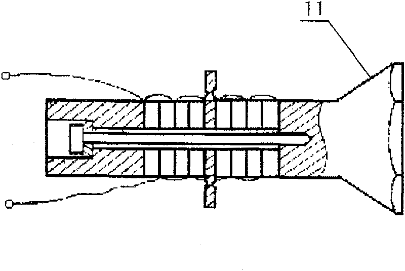
[0039] The stacked wafer emission transducer of this example comprises piezoelectric wafer stack 2, front cover plate 1, backing 5, prestressed screw 6, waterproof sound-permeable layer 8 and output cable 7 etc., as Figure 6 shown.

[0040] In the piezoelectric wafer stack 2, the wafers are made of piezoelectric ceramic PZT with a hole in the center, and the polarization directions of every two adjacent wafers are opposite (see Figure 8 ). Between the chips, and between the chip and the front cover 1 and the backing 5, a thin metal sheet 3 is clamped to weld the leads 4. The wafer, the metal sheet 3, the front cover 1 and the backing 5 are glued together with epoxy resin. Die stack wiring such as Figure 8 As shown, a parallel connection is used to ensure that the same phase voltage is applied to each chip at ...


PUM


Abstract

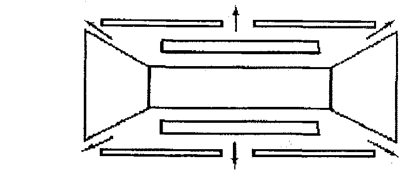
The invention provides a stacked wafer transmission transducer which comprises a piezoelectric stacked wafer, a front cover plate and a back lining, wherein the piezoelectric stacked wafer is formed by stacking a plurality of piezoelectric ceramic wafers, the front cover plate is made of light metal, the back lining is made of heavy metal, the front cover plate and the back lining are respectivelypositioned at the top and the bottom ends of the piezoelectric stacked wafer, metal sheets are sandwiched between adjacent wafers and between the piezoelectric stacked wafer and the front cover plateor the back lining to weld electrode leads; and the polarization direction of the piezoelectric stacked wafer is along the thickness direction. The invention is characterized in that: the front coverplate is pyramidal with a cyclonical head and comprises upper and lower portions, wherein the lower portion is an upside-down trumpet-shaped bench and the upper portion is a cylinder with a planar orspherical top surface. The invention maintains the characteristics of large sound-energy density of stacked wafer oscillators, utilizes the pyramidal front cover plate with the cylindrical head to enlarge the transmitted beam angle of the transducer, and can adjust the transmitted beam angle by changing shape and size of the front cover plate.

Description

technical field [0001] The invention belongs to the technical field of underwater acoustic detection, and in particular relates to a transmitting transducer which uses the piezoelectric effect of piezoelectric ceramics to transmit underwater acoustic signals to realize underwater detection, and can be widely used in underwater communication, detection, target positioning, tracking, etc. , is an important component used by sonar. Background technique [0002] The underwater acoustic transducer is a device that converts sound energy and electrical energy into each other. Its status is similar to that of an antenna in radio equipment, and it is a key device for transmitting and receiving sound waves underwater. Underwater detection, identification, communication, as well as marine environment monitoring and the development of marine resources are inseparable from underwater acoustic transducers. Transducers can be divided into transmitting type, receiving type and dual-purpose...

Claims


Application Information

Patent Timeline
Patent Type & Authority Patents(China)
IPC IPC(8): B06B1/06G10K9/122G10K11/00
Inventor 王丽坤秦雷李莉张金铎
Owner BEIJING INFORMATION TECH INST
Learn More