

LED lighting device
A technology of light-emitting diodes and lighting devices, which is applied to lighting devices, components of lighting devices, and damage prevention measures for lighting devices. Enhanced optical brightness, improved optical uniformity, and improved light uniformity
Inactive Publication Date: 2010-12-01
HONG FU JIN PRECISION IND (SHENZHEN) CO LTD +1
View PDF0 Cites 0 Cited by
- Summary
- Abstract
- Description
- Claims
- Application Information
AI Technical Summary
Problems solved by technology
However, even if the above-mentioned side-lit LED light source 13 is matched with the LED top reflector 15, the light beam emitted by the LED light source 13 is fully mixed in the space formed by the first reflective element 14 and the lamp cover L6, and the adjacent LED light source 13 There are still obvious dark areas between
That is to say, the point light source cannot be effectively converted into a uniform surface light source, so the brightness of the emitted light from the LED lighting device 10 is uneven.
To sum up, the above phenomena will lead to a decline in the quality of LED lighting devices
Method used
View moreImage
Smart ImageViewing Examples

Examples
Embodiment Construction
Login to View More PUM
 Abstract
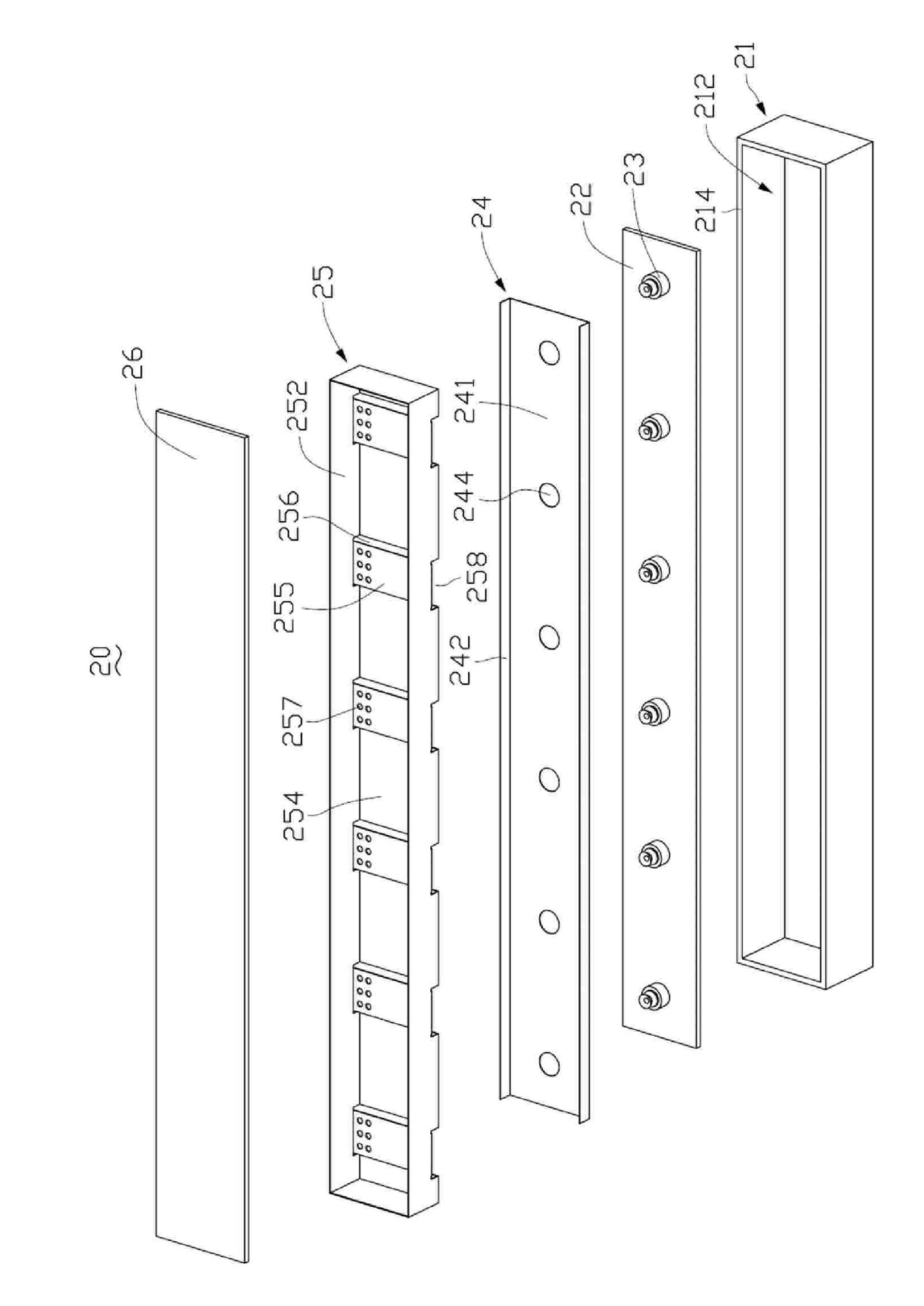
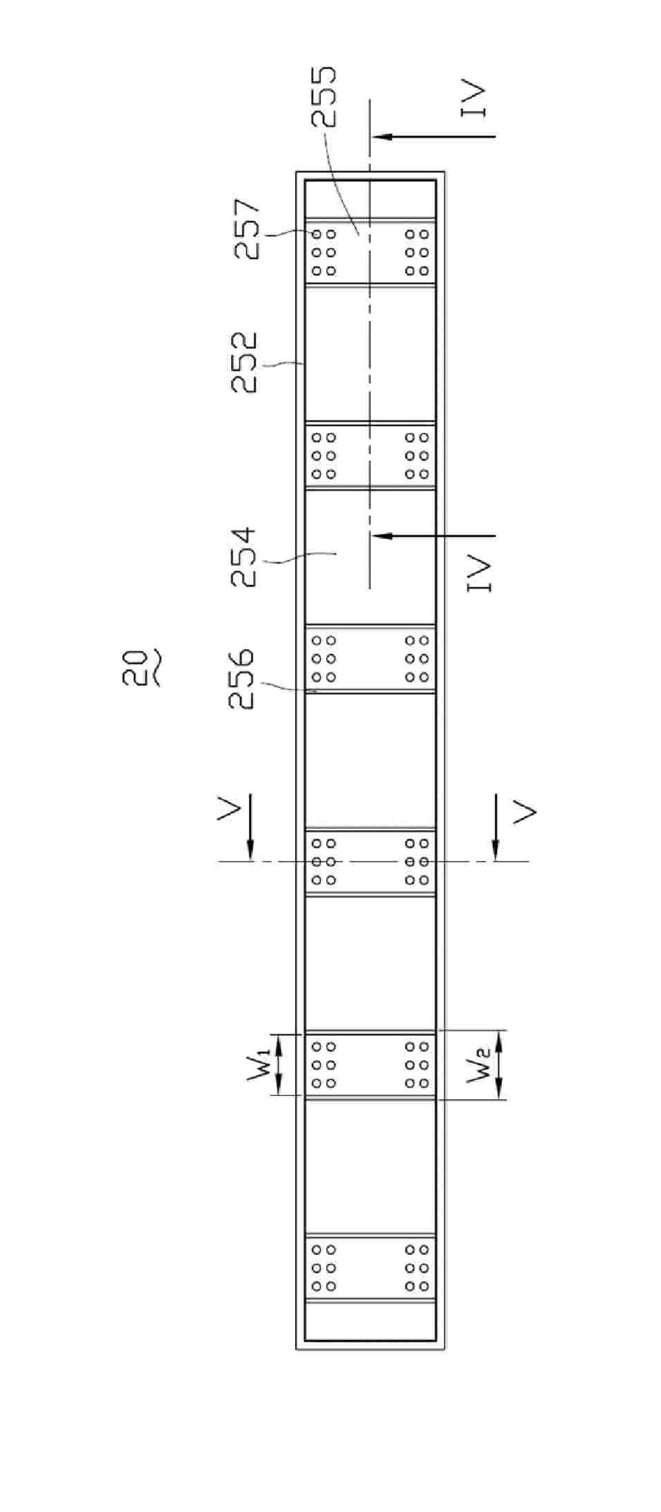
The invention discloses a LED illumination device, including a lamp house, a circuit board, an LED source, a first reflecting element, a second reflecting element and a light cover, wherein the circuit board is arranged on the bottom of the lamp house and the LED source is electrically connected on the surface of the circuit board. The first reflecting element is a reflecting board, on which at least a via hole is arranged corresponding to the LED source passing through the via hole. The second reflecting element includes a bottom board, from which at least two opposite side walls are formed and at least a mat film corresponding to the LED source. The mat film extends from one side wall to the center of the side wall. A plurality of loophones are arranged on the side walls near the mat film and the bottom board has at least a first opening corresponding to the mat film, which covers the corresponding LED lamp-house. The lamp cover is covered at the opening of the lamp house. The illumination device has better optical property.
Description
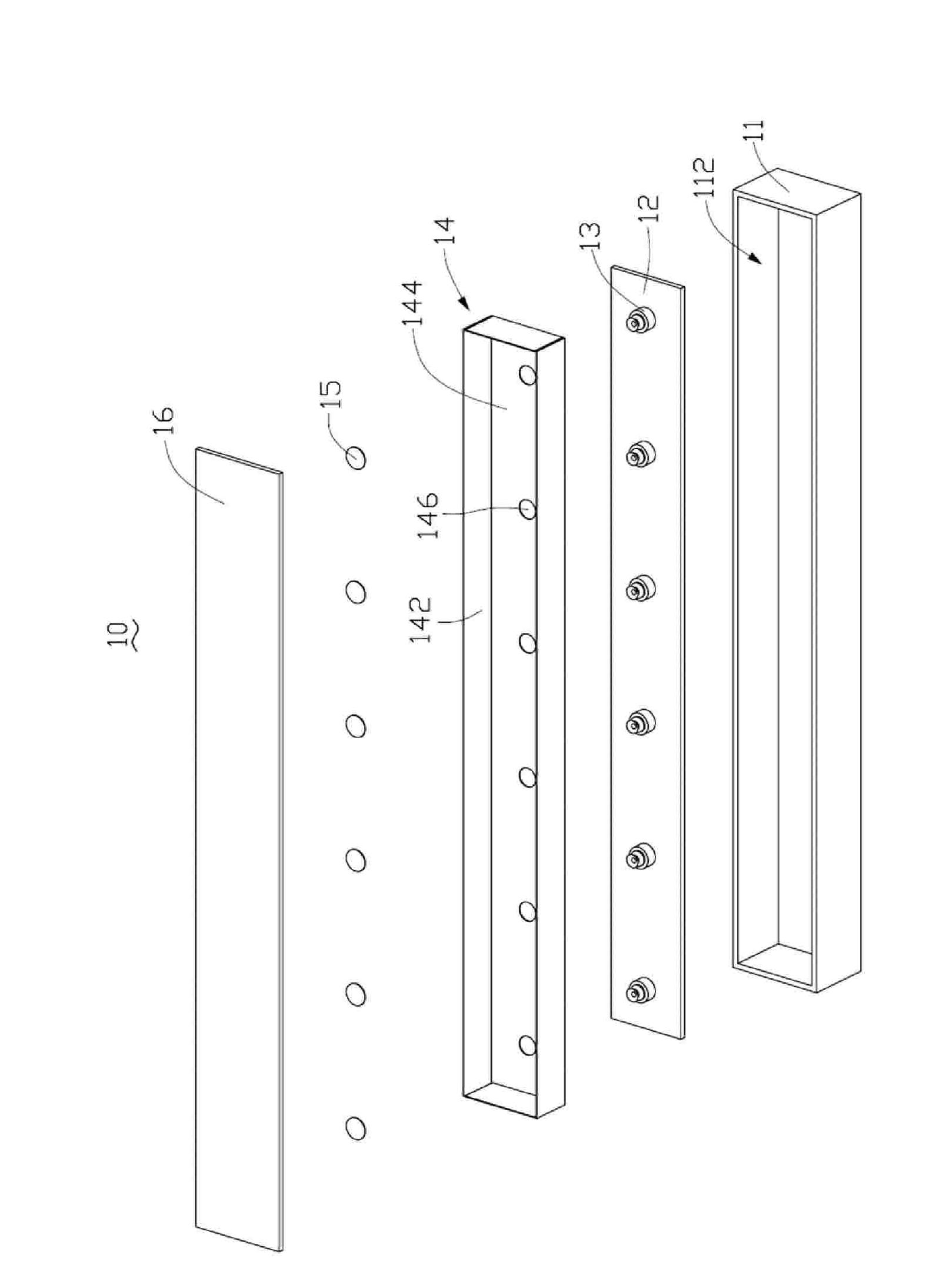
LED lighting device technical field The invention relates to an illuminating device, in particular to an illuminating device using a light emitting diode. Background technique Light Emitting Diode (LED) has the characteristics of environmental protection, high mechanical reliability and high service life, so it is a new trend to use LED as the light source of the lighting device. Please refer to FIG. 1 , which shows a conventional elongated LED lighting device 10 (hereinafter referred to as LED lighting device). The LED lighting device 10 includes a light box 11 , a circuit board 12 , a side-light LED light source 13 , a reflector 14 , an LED top reflector 15 and a lamp cover 16 . The light box 11 is a hollow strip structure with an opening 112 . The circuit board 12 is also strip-shaped, and is correspondingly arranged on the bottom of the light box 11 . The plurality of edge-lit LED light sources 13 are electrically connected and arranged on the upper surface of the ...
Claims
Login to View More Application Information
Patent Timeline
 Patent Type & AuthorityPatents(China)
IPC IPC(8): F21S2/00F21V15/02F21V17/00F21V7/00F21V5/02F21V7/22F21V11/14F21Y101/02
CPCF21V11/12F21V13/10G02F1/133603F21Y2101/02G02F1/133611F21V11/14G02F1/133605F21V13/12F21Y2115/10
Inventor章绍汉
OwnerHONG FU JIN PRECISION IND (SHENZHEN) CO LTD