Anti-burn cupping glasses

A technology of cupping and anti-burn, which is applied in the field of cupping, and can solve the problems of patients' burns and burning dust burns on affected parts

Inactive Publication Date: 2008-10-08
俞钟晓
View PDF0 Cites 2 Cited by
  • Summary
  • Abstract
  • Description
  • Claims
  • Application Information

AI Technical Summary

Problems solved by technology

However, when the neck is used facing the ground, because any part of the inner wall of the tank is always above the neck of the tank, once the doctor's time is not properly controlled, the burning dust will burn the affected area; it is easy to make the patient feel the fear of being burned; this operation seems to be necessary Impossible by a senior doctor

Method used


Image

  • Anti-burn cupping glasses
  • Anti-burn cupping glasses
  • Anti-burn cupping glasses

Examples


Embodiment Construction

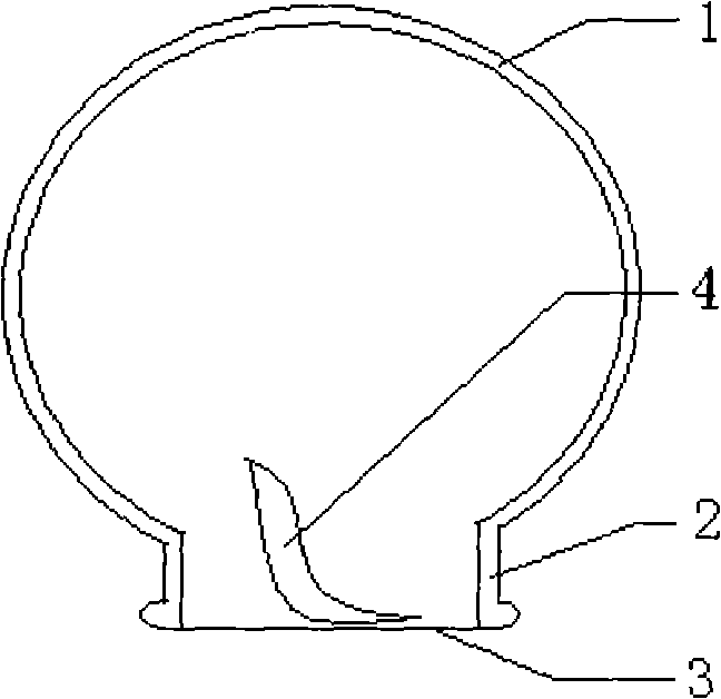
[0015] The present invention will be further described below in conjunction with the accompanying drawings. Talk about it with the suction port facing the ground. figure 1 As shown, the existing cupping is an integrated transparent glass body composed of a tank chamber 1, a tank neck 2, and a suction port 3. Any place of its inner wall of the tank cavity 1 is always above the tank neck 2, and the burning dust 4 falls to the affected part during use.

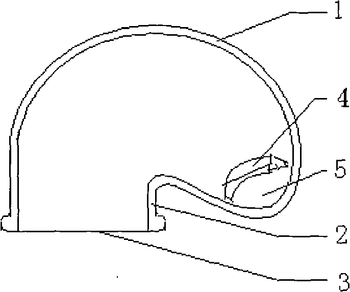
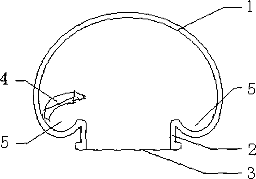
[0016] An anti-burn cupping cup of the present invention is an integrated transparent glass body, including a tank cavity 1, a tank neck 2, and a suction port 3. The inner wall of the tank cavity 1 is formed on the cross-connecting area with the tank neck 2 to accommodate The depression 5 of burning dust 4. When the suction port 3 is downward, the burning dust 4 is placed on the depression 5 of the inner wall of the tank cavity 1, so as not to fall to the affected part so as to avoid the accident of burning the skin. figure 2...


PUM


Abstract

An anti-burn cupping comprises a cupping cavity (1), a cupping neck (2) and a pull-in port (3). A depression (5) which is big enough for accommodating combustion dusts is formed on the cross connecting area of the inner wall of the cupping cavity (1) and the cupping neck (2). The depression (5) is formed by surrounding the cupping neck (2). The cupping neck (2) is in a cone shape. The anti-burn cupping has the advantages of good anti-burn effect and simple structure.

Description

technical field [0001] The invention relates to a medical and health care device, in particular to an anti-burn cupping cup. Background technique [0002] Cupping therapy is a commonly used method of physical therapy in traditional Chinese medicine, that is, a burning paper is placed in the cupping cup, and the air in the cup is heated and expelled, and at the same time, the negative pressure in the cup is used to cover the mouth of the cup on the affected area, and the suction is absorbed by the negative pressure. Qi and waste heat radiation to achieve therapeutic purposes. However, when the neck is used facing the ground, because any part of the inner wall of the tank is always above the neck of the tank, once the doctor's time is not properly controlled, the burning dust will burn the affected area; it is easy to make the patient feel the fear of being burned; this operation seems to be necessary It cannot be done by a senior doctor. Contents of the invention [0003]...

Claims


Application Information

Patent Timeline
Patent Type & Authority Applications(China)
IPC IPC(8): A61H7/00A61M1/08
Inventor 俞钟晓
Owner 俞钟晓
Why Eureka
Try Eureka