
Solid electrolytic capacitor and manufacturing method thereof

A technology of solid electrolysis and solid electrolyte layer, which is applied in the direction of solid electrolytic capacitors, capacitor electrodes, capacitor parts, etc., can solve the problems of large change, increase of interface resistance, increase of intrinsic resistance, etc., and achieve the effect of small change over time

Active Publication Date: 2011-01-19
PANASONIC CORP
View PDF1 Cites 0 Cited by
  • Summary
  • Abstract
  • Description
  • Claims
  • Application Information

AI Technical Summary

Problems solved by technology

Therefore, the resistance of the interface between the solid electrolyte layer 3 and the carbon layer 4A increases.
In addition, external oxygen or moisture intruding from the gap between the carbon layer 4A and the solid electrolyte layer 3 causes an increase in the intrinsic resistance of the solid electrolyte layer 3 itself.
As a result, the ESR of a solid electrolytic capacitor changes with time and tends to increase

Method used


Image

  • Solid electrolytic capacitor and manufacturing method thereof
  • Solid electrolytic capacitor and manufacturing method thereof
  • Solid electrolytic capacitor and manufacturing method thereof

Examples


Embodiment approach 1

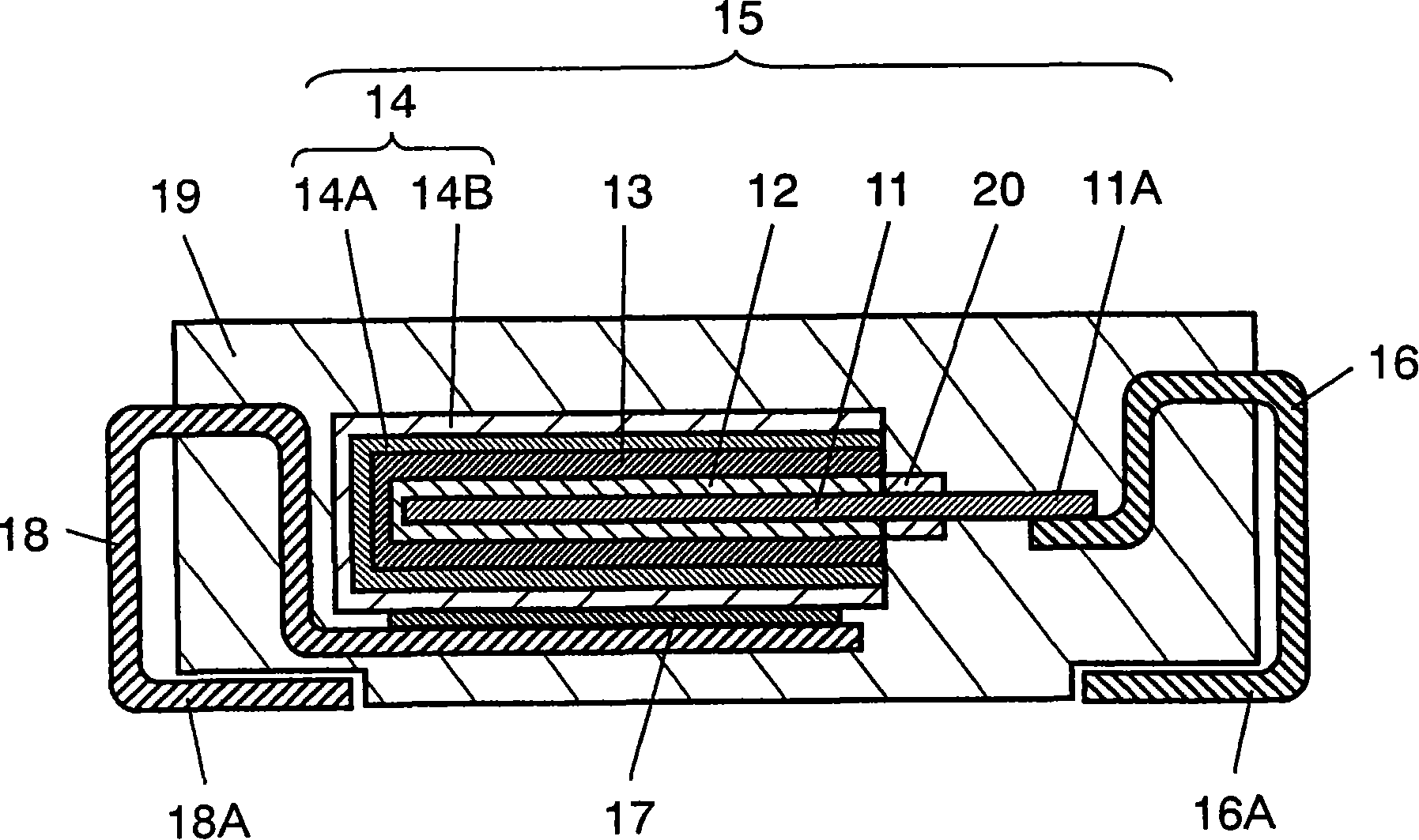
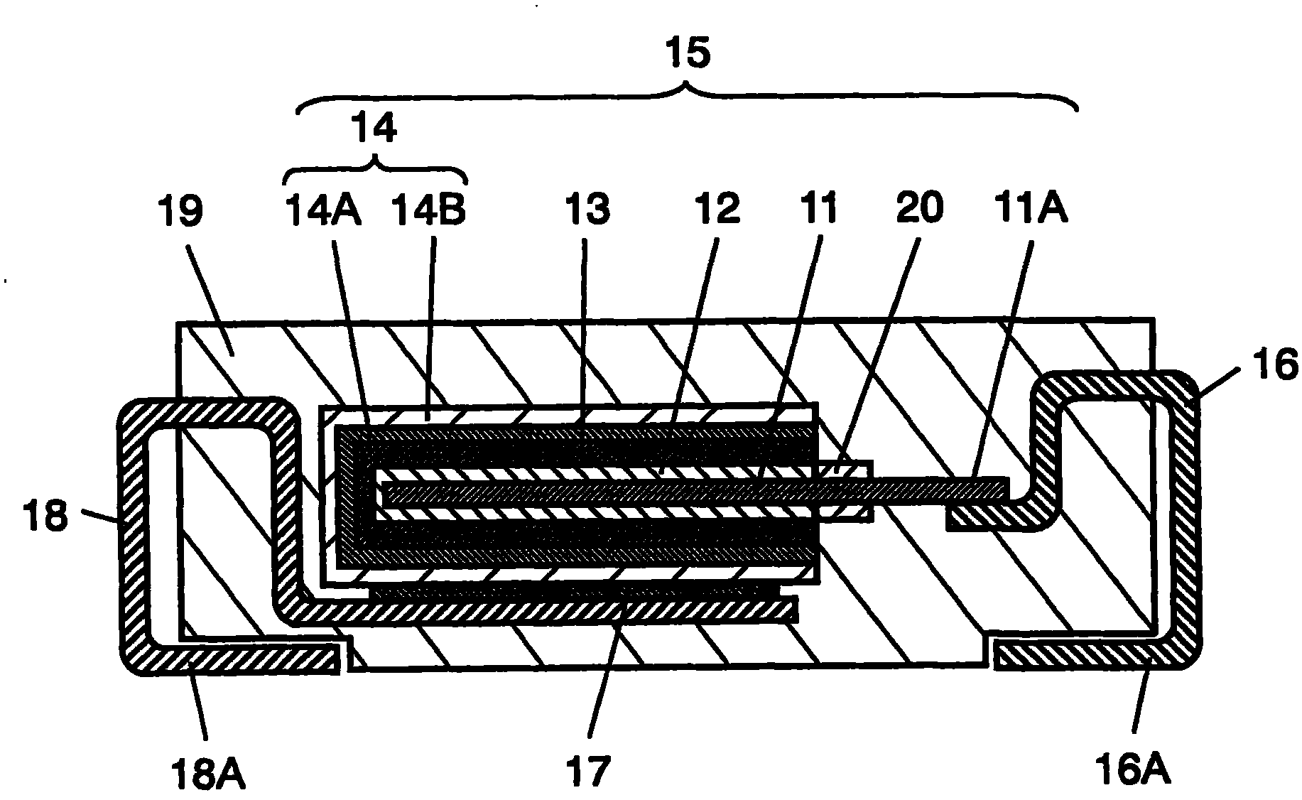
[0015] figure 1 is a cross-sectional view showing the configuration of an aluminum electrolytic capacitor as an example of the solid electrolytic capacitor in the first embodiment. This solid electrolytic capacitor has a capacitive element 15 , an anode terminal 16 , a cathode terminal 18 , and an exterior resin 19 . The capacitive element 15 is composed of an anode body 11 , a dielectric oxide film layer 12 , a solid electrolyte layer 13 and a cathode layer 14 .

[0016] The anode body 11 is made of a valve metal foil such as aluminum, and its surface is roughened by etching to increase its surface area. In addition, the end part also serves as the anode lead-out part 11A. The anode lead-out portion 11A and the anode body 11 are separated by an insulating resist material 20 adhered to the surface of the foil. Dielectric oxide film layer 12 is formed by chemical conversion treatment of the surface of anode body 11 .

[0017] Solid electrolyte layer 13 is formed on the sur...

Embodiment approach 2

[0080] In the solid electrolytic capacitor according to the present embodiment, the carbon layer 14A contains the second additive instead of the first additive in the first embodiment. The second additive is composed of at least one selected from aromatic sulfonic acid formaldehyde condensate, aromatic sulfonic acid formaldehyde condensate salt, polystyrenesulfonic acid, and polystyrenesulfonate. Other configurations and uses figure 1 Embodiment 1 described is the same, so only different points will be described.

[0081] Specific examples of the second additive include arylphenolsulfonic acid formaldehyde condensate, phenolsulfonic acid formaldehyde condensate, anthraquinonesulfonic acid formaldehyde condensate, naphthalenesulfonic acid formaldehyde condensate, polystyrenesulfonic acid, and their sodium salts. Wait.

[0082] The solid electrolytic capacitor according to this embodiment can be manufactured by the same method using the second additive instead of the first ad...


PUM

PropertyMeasurementUnit
melting pointaaaaaaaaaa

Abstract

A carbon layer is formed on a solid electrolyte layer of the solid electrolytic capacitor, and a conductor layer connected to a cathode terminal is further disposed thereon. The carbon layer contains carbon particles, and a first additive or a second additive. The first additive is formed from at least one of those selected from the group consisting of hydrated silica and silicate. The second additive is formed from at least one of those selected from the group consisting of a condensation product of an aromatic sulfonic acid with formaldehyde, a condensation product of an aromatic sulfonate with formaldehyde, polystyrene sulfonic acid, and polystyrene sulfonate.

Description

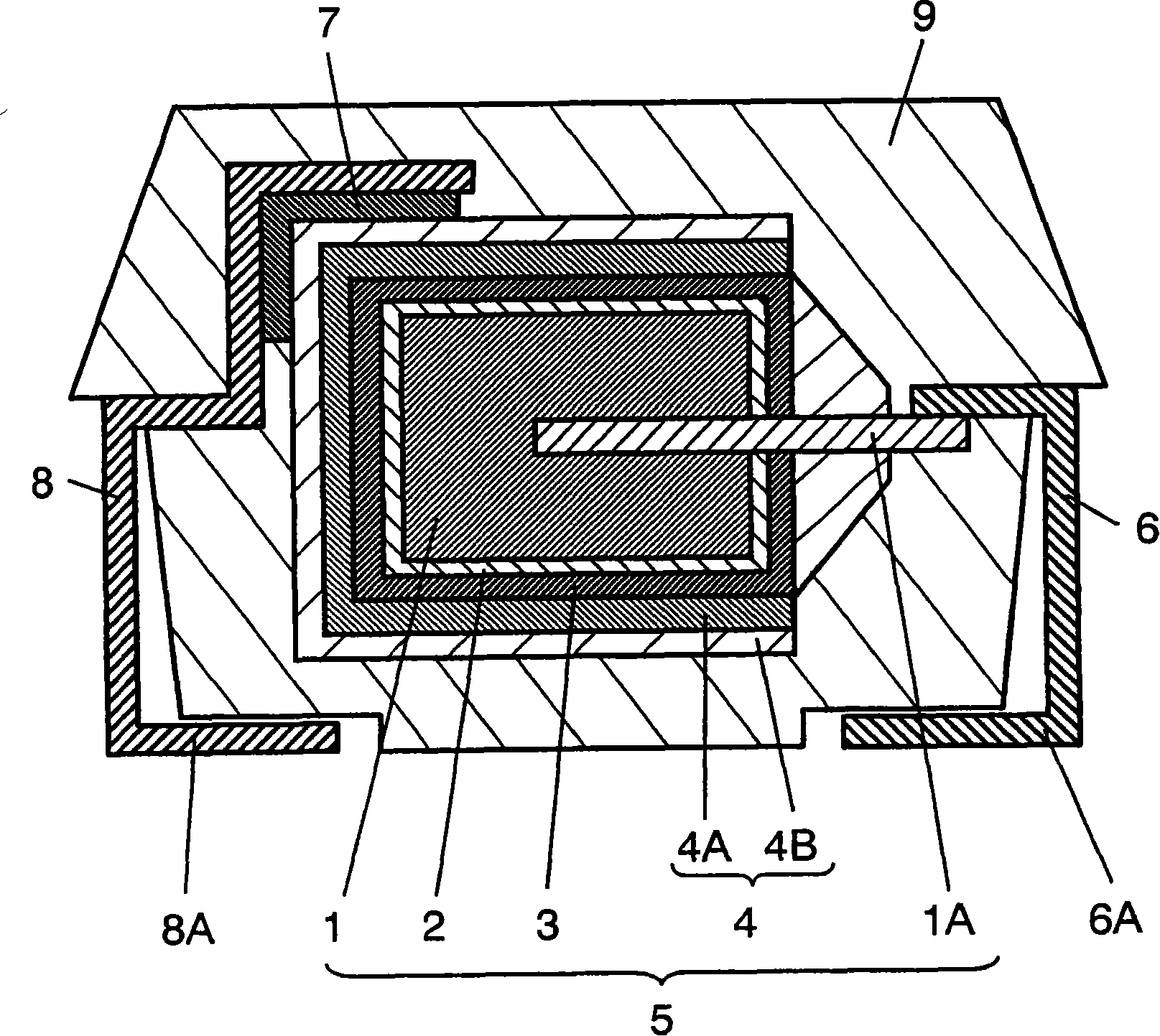
technical field [0001] The present invention relates to a solid electrolytic capacitor used in various electronic instruments and its manufacturing method. [0002] 4 Background technique [0003] In recent years, along with the development of digital devices, there has been a strong demand for capacitors with low equivalent series resistance (hereinafter referred to as ESR) and excellent high-frequency characteristics. In response to such demands, capacitors using solid electrolyte layers such as manganese dioxide, polypyrrole, and polythiophene as electrolytes have been developed and commercialized. [0004] figure 2 It is a cross-sectional view of a conventional solid electrolytic capacitor. This solid electrolytic capacitor has a capacitive element 5 , an anode terminal 6 , a cathode terminal 8 , and an exterior resin 9 . The capacitive element 5 is composed of an anode body 1 , a dielectric oxide film layer 2 , a solid electrolyte layer 3 and a cathode layer 4 . ...

Claims


Application Information

Patent Timeline
Patent Type & Authority Patents(China)
IPC IPC(8): H01G9/04H01G9/15
Inventor 盛博美松浦裕之齐藤佳津代小泽正人
Owner PANASONIC CORP
Learn More