Remote monitoring system

A technology of remote monitoring and monitoring devices, which is applied in the field of remote monitoring systems, and can solve problems such as the inability of the monitoring center to communicate, the overall impact of the remote monitoring system, and the difficulty in ensuring the safety of monitored objects.

Active Publication Date: 2008-11-05
TOSHIBA ELEVATOR KK
View PDF0 Cites 14 Cited by
  • Summary
  • Abstract
  • Description
  • Claims
  • Application Information

AI Technical Summary

Problems solved by technology

As a result, the monitoring center is unable to communicate due to excessive communication load
[0007] When such a situation occurs, even if a signal of the occurrence (such as an emergency call signal from the car or a request signal from a customer, etc.) , and therefore cannot receive these signals
Therefore, it may have a great impact on the remote monitoring system as a whole, and it is difficult to ensure the safety of the monitored objects

Method used


Image

  • Remote monitoring system
  • Remote monitoring system
  • Remote monitoring system

Examples


no. 2 approach

[0073] Next, a second embodiment of the present invention will be described.

[0074] In the second embodiment, in the case of monitoring monitoring objects 1 spread over a wide area, ..., or having a plurality of monitoring objects 1 for each monitoring area (such as Tokyo, Kanagawa, etc.) The remote monitoring system realizes effective structure.

[0075] refer to image 3 Be explained.

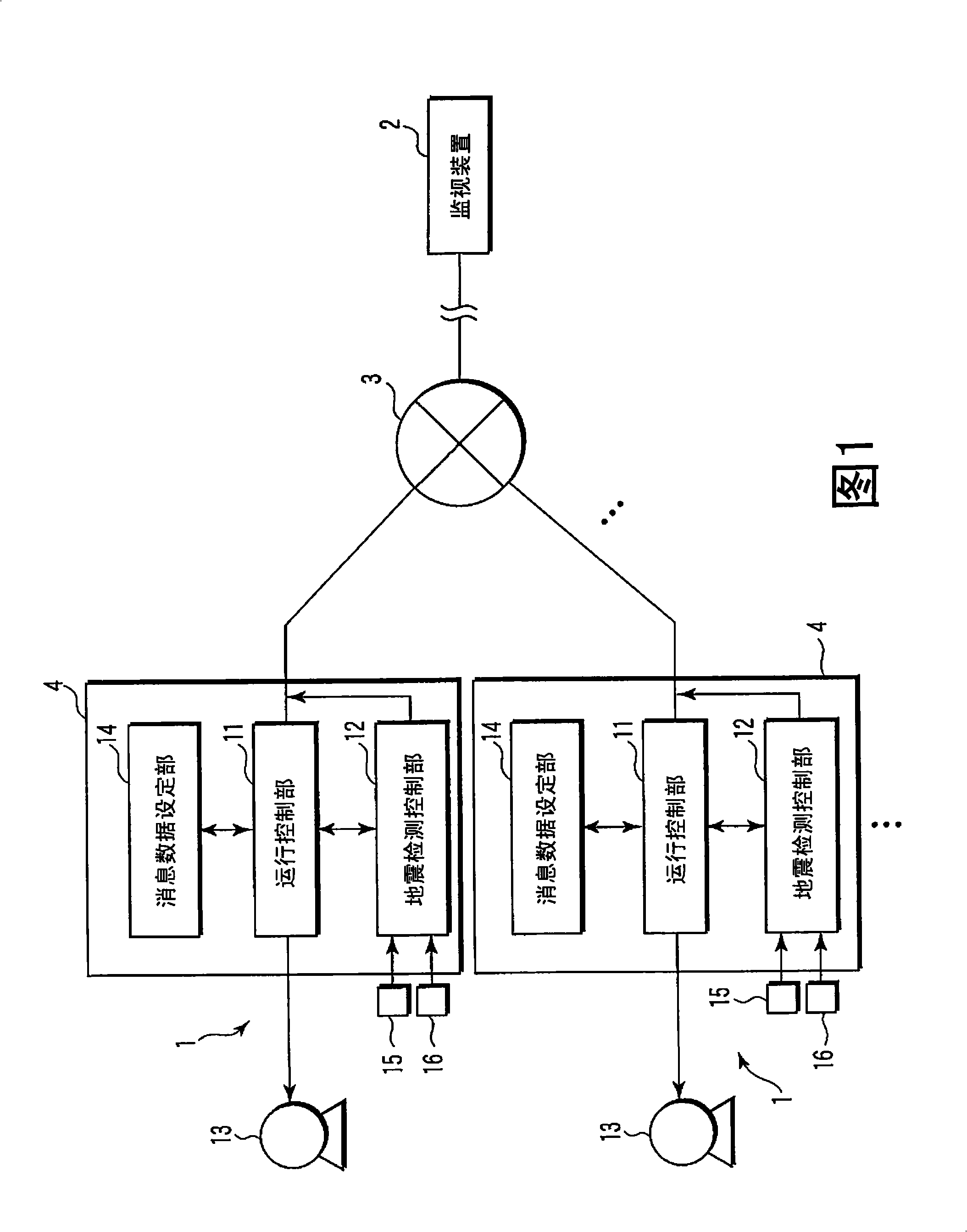
[0076] A plurality of monitoring devices 2, . . . are installed in the monitoring center. Since each monitoring device 2 has a plurality of monitored objects 1 in each monitored area, it separates each monitored area and performs distributed monitoring. That is, a certain monitoring device 2 monitors the Tokyo metropolitan area, and another monitoring device 2 monitors the Kanagawa prefecture area.

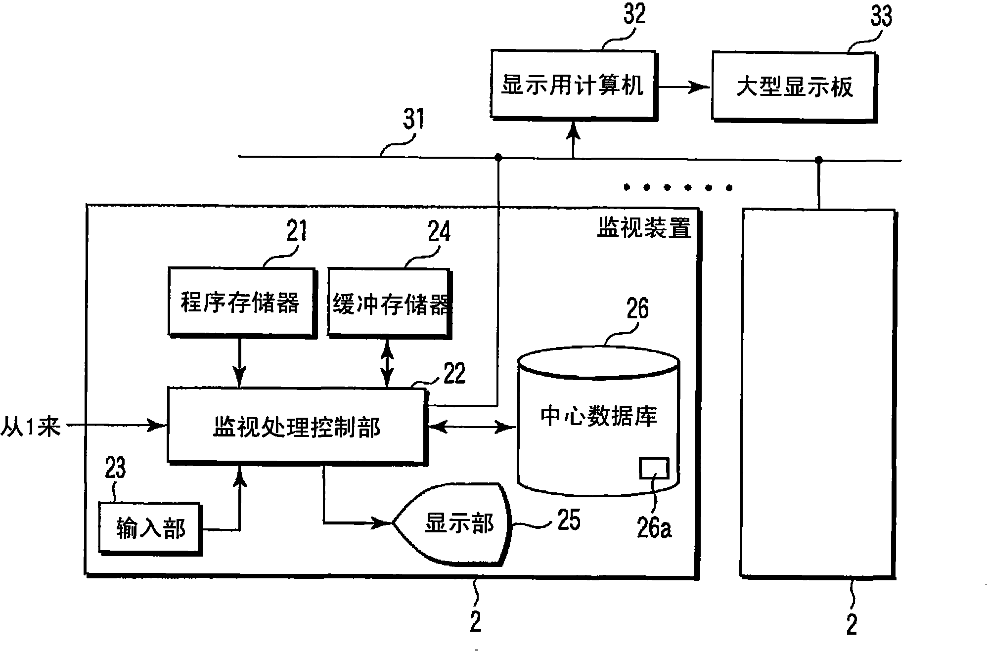
[0077]Here, in the second embodiment, each monitoring device 2, . In addition, a large display panel 33 is connected to the internal network 31 via a display computer 32 . The computer 32...


PUM


Abstract

A remote monitoring system includes: an earthquake detection control unit (12) for an object to be monitored, the unit having earthquake sensors (15, 16) for detecting a first and a second signal transmitted with a time difference upon occurrence of an earthquake, a controlled operation start signal generation unit for transmitting a switching signal to start a controlled operation mode of an elevator to an operation control unit (11) upon detection of the first signal, an elevator stop instruction signal generation unit for transmitting an elevator stop instruction signal to the operation control unit (11) upon detection of the second signal, and an earthquake detection signal transmission unit for transmitting the sensor detection signal via a communication line (3) upon detection of the second signal; and a monitoring device (2) connected to the communication line (3) for monitoring the sensor detection signal transmitted from the earthquake detection control unit (12).

Description

technical field [0001] The present invention relates to a remote monitoring system for monitoring remote objects from a monitoring center. Background technique [0002] In the past, in order to grasp the impact of earthquakes on remote monitoring objects, P-wave seismic sensors and S-wave seismic sensor. [0003] Such as Figure 11 As shown in the conceptual diagram of , the P wave 101 is called a longitudinal wave or a density wave, and is a small shock wave that passes through the rock plate 103 from the seismic source 102 that destroys foundations and the like, and reaches the building 104 first. The S wave 105 is called a shear wave, and is a large shaking wave transmitted through the rock plate 103 after the arrival of the P wave. The P wave varies depending on the density and rigidity (a type of hardness) of the foundation, but it is said that the speed of the P wave is about 6 km per second, and the speed of the S wave is 3.5 km per second. That is, the P wave spee...

Claims


Application Information

Patent Timeline
Patent Type & Authority Applications(China)
IPC IPC(8): B66B5/02B66B3/00B66B5/00G08B21/10G08B25/14
CPCB66B5/021B66B5/022
Inventor 幡野一寻小谷敏之铃木孝夫
Owner TOSHIBA ELEVATOR KK
Why Eureka
Try Eureka