Supercharge Your Innovation With Domain-Expert AI Agents!

Drying system for a hair removing device

一种烘干系统、毛发去除的技术,应用在烘干系统领域,能够解决很差烘干效率、多烘干时间等问题

Inactive Publication Date: 2008-11-19
MATSUSHITA DENKO KK
View PDF2 Cites 2 Cited by
  • Summary
  • Abstract
  • Description
  • Claims
  • Application Information

AI Technical Summary

Problems solved by technology

Under this structure, there is still the following problem, that is, it is difficult for the air flow to directly enter the inside of the cutter head, resulting in poor drying efficiency or requiring a lot of drying time

Method used


Image

  • Drying system for a hair removing device
  • Drying system for a hair removing device
  • Drying system for a hair removing device

Examples


Embodiment Construction

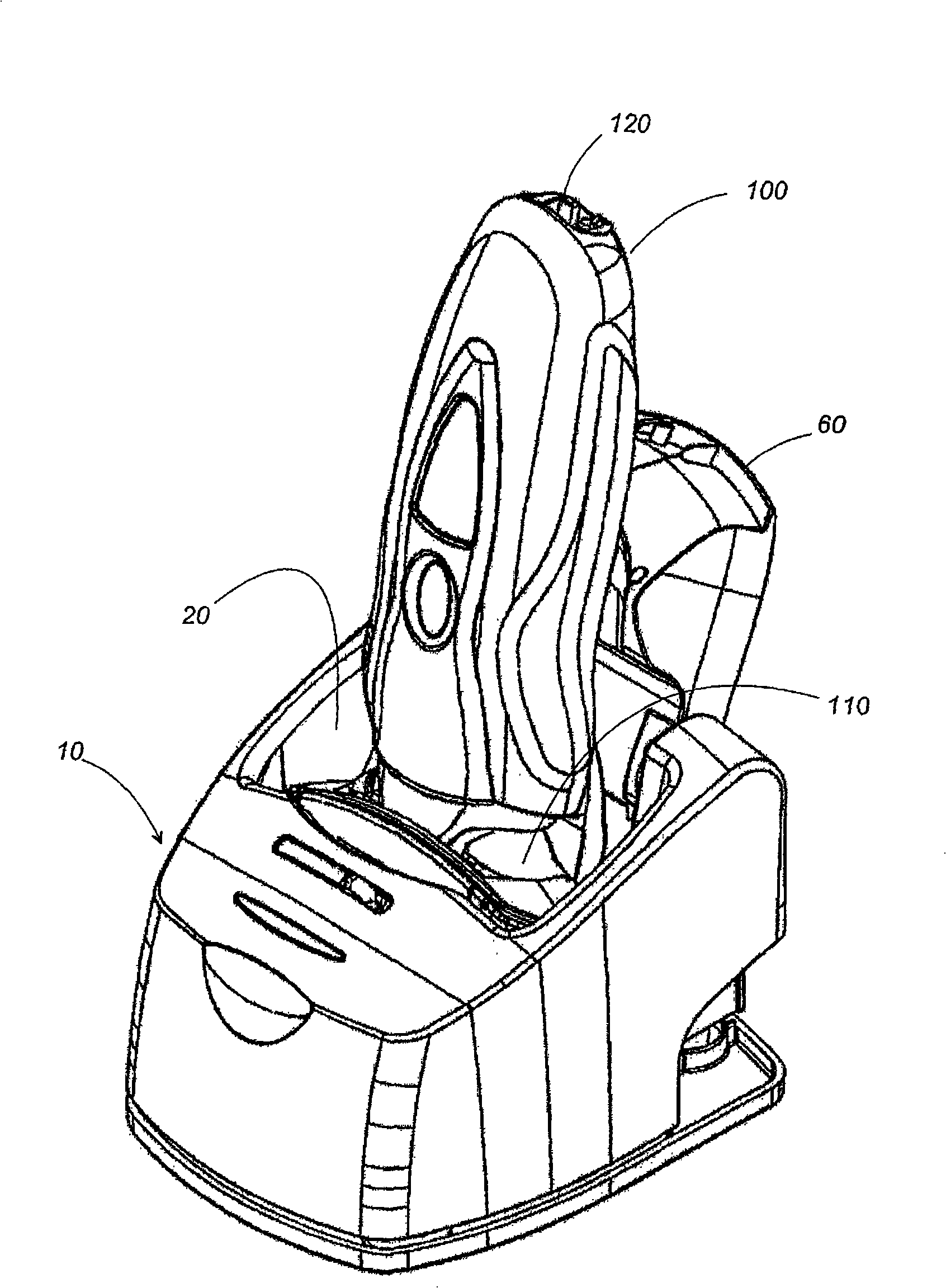
[0025] now refer to Figure 1 to Figure 5 , which shows a drying system for a hair removal device according to a preferred embodiment of the present invention. In this embodiment, a dry shaver 100 is shown as a typical example of a hair removal device having a washable head 110 and a rechargeable battery 130 for driving the inner blades. However, the drying system is equally applicable to other types of hair removal devices, including epilators with perforated heads and the like.

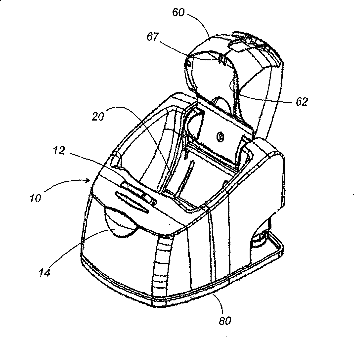
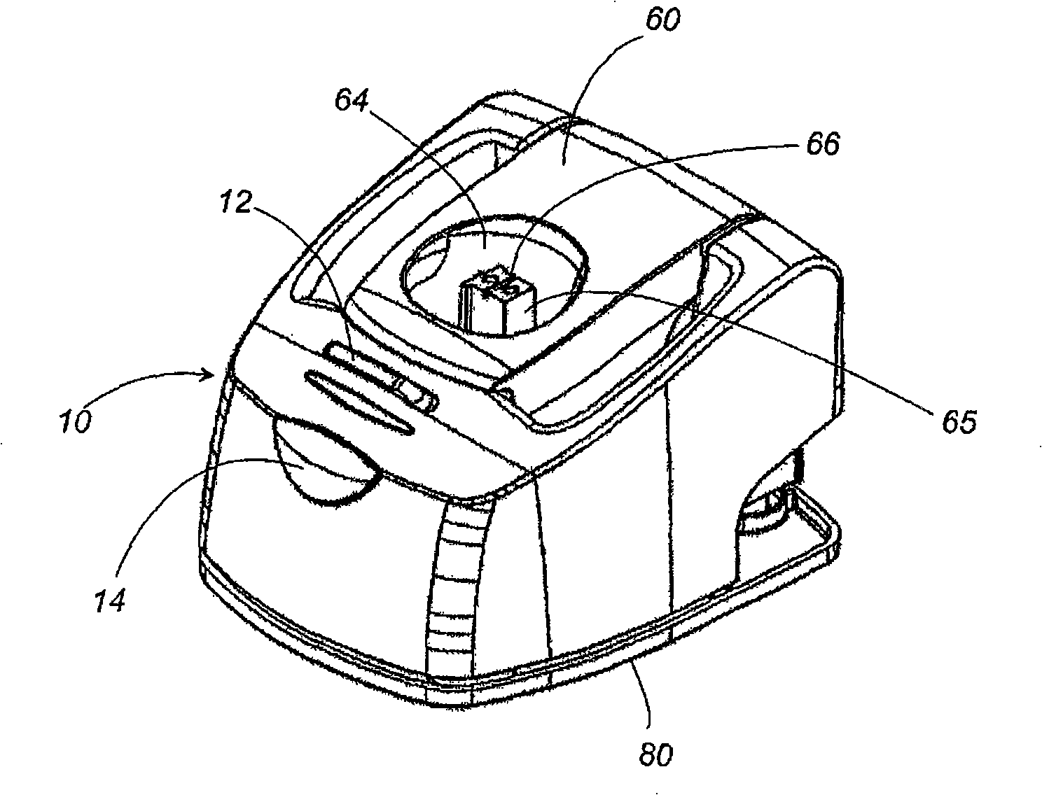
[0026] The drying system has a housing 10 configured with a drying chamber 20 for detachably receiving a head 110 of a shaver. The shell 10 is provided with a heater 30 and a blower 40 , the heater 30 is used to heat the cutter head, and the blower 40 is used to generate a forced air flow for drying or cooling the cutter head 110 . like Figure 2A and 2B As shown, the lid 60 is pivotally connected to the upper end of the housing 10 so as to be movable between an open position which opens the dry...


PUM


Abstract

A drying system for a hair removing device is capable of effectively drying the cutter head. The drying system includes a casing having a dry chamber configured to detachably receive a cutter head of the hair removing device, a heater for heating the cutter head; and a blower for generating a forced air flow and drying the cutter head. The casing is formed with an air flow channel configured to direct the forced air flow towards the cutter head. A tray is provided to define the bottom of the dry chamber and bear the cutter head. The tray is formed with a draft port through which the flow channel communicates into the dry chamber so that the forced air flow can be directed straight to the cutter head for effectively cooling or drying the cutter head.

Description

technical field [0001] The invention relates to a drying system for a hair removal device, in particular an electric shaver. Background technique [0002] Washable hair removal devices already exist in the prior art which have the advantage of being easy to clean. In this regard, there is a need to heat the cutter head for disinfection after cleaning it. In order to meet this demand, Japanese Patent Publication No. 2005-199083 proposes a heating stand having a function of heating the cutter head while the hair removing device is held on the stand. However, it has been found that heat alone is not sufficient to dry the tips and is preferably used in combination with air blast. Accordingly, it would be desirable to provide a drying system having a combination heater and blower. Such a drying system can be provided as a drying chamber with an open top, in which the cutter head is exposed selectively or in combination to heat and blast, as partly described in the prior art pu...

Claims


Application Information

Patent Timeline
Patent Type & Authority Applications(China)
IPC IPC(8): A45D27/46A45D27/48
CPCA45D27/48
Inventor 上田泰教重田一也伊吹康夫
Owner MATSUSHITA DENKO KK
Features
  • R&D
  • Intellectual Property
  • Life Sciences
  • Materials
  • Tech Scout
  • Unparalleled Data Quality
  • Higher Quality Content
  • 60% Fewer Hallucinations
Learn More