
Nut for reinforcing bar

A technology of steel bars and nuts, applied in the direction of structural elements, building components, building reinforcements, etc., can solve problems such as construction obstacles, achieve the effect of ensuring fastening strength and reducing protruding parts

Inactive Publication Date: 2012-04-04
TAMA HOME
View PDF0 Cites 0 Cited by
  • Summary
  • Abstract
  • Description
  • Claims
  • Application Information

AI Technical Summary

Problems solved by technology

Therefore, the bolts and nuts protrude too much from the two end faces of the wall prefabricated panel group, sometimes becoming an obstacle during construction

Method used


Image

  • Nut for reinforcing bar
  • Nut for reinforcing bar
  • Nut for reinforcing bar

Examples


Embodiment Construction

[0022] Embodiments of the present invention will be described below with reference to the drawings.

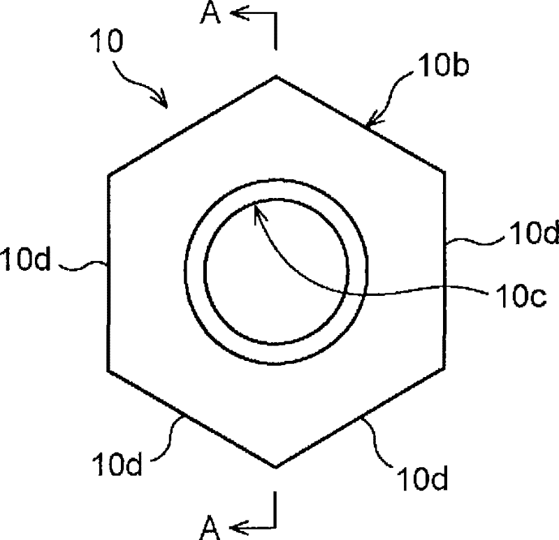
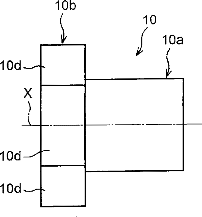
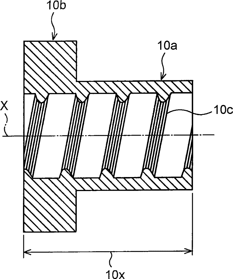
[0023] Such as Figure 1A , Figure 1B , figure 2 As shown, the nut 10 for reinforcing bars of the present embodiment includes: a cylindrical main body portion 10a, a regular hexagonal flange 10b formed on one end portion of the main body portion 10a, and an inner peripheral surface of the flange 10b. Formed internal thread portion 10c. Such as Figure 3A , Figure 3B , Figure 3C , Figure 4 As shown, the main body part 10a can be inserted into the through hole 12 and the concave part 13 formed on the concrete prefabricated panel 11, and the internal thread part 10c formed on the inner peripheral surface of the main body part 10a can be connected with the through hole 12 and the recessed part 13. The outer threaded parts 14a, 15a of the reinforcement members 14, 15 of the recess 13 are screwed together (refer to Figure 5 , Figure 7 ).

[0024] On the outer periphe...


PUM


Abstract

A nut for reinforcing bar capable of stably holding its screwed state with a reinforcing bar and enabling the reduction of its projected portion from the end face of a structural body. The nut (10) for reinforcement comprises a cylindrical body part (10a), a regular hexagonal flange (10b) formed at one end of the body part (10a), and a female screw part formed in the inner peripheral surface of the flange (10b). The body part (10a) is insertable into a through hole formed in a concrete block, and the female screw part formed in the inner peripheral surface of the body part (10a) can be screwed onto a male screw part formed on the outer periphery of the reinforcing bar inserted into the through hole. Three pairs of flat parts (10d) parallel with each other with respect to the center axis (X) of the body part (10a) are formed on the outer periphery of the right diagonal flange (10b). The length of the female screw part in the inner peripheral surface of the body part (10a) in the direction of the center axis (X) is approximately four times the screw pitch of the male screw part on the outer periphery of the reinforcing bar.

Description

technical field [0001] The present invention relates to a nut for reinforcing bars used for fixing a reinforcing member as a component of a prefabricated concrete slab structure or applying tension to the reinforcing member. Background technique [0002] When a plurality of prefabricated concrete slabs are combined vertically and horizontally to construct a structure such as a wall, in order to ensure its strength, steel members are often made to pass through the prefabricated concrete slabs stacked vertically. At this time, since the strength is further improved by making the prefabricated concrete slabs stacked in close contact with each other, a technique of screwing nuts on the ends of the reinforcement members exposed from the end faces of the prefabricated concrete slabs and fastening them has been proposed (for example, refer to Patent Document 1 - Japanese Patent Application Publication No. 34-3622). [0003] In the "load-bearing wall construction method" described ...

Claims


Application Information

Patent Timeline
Patent Type & Authority Patents(China)
IPC IPC(8): E04B2/02
CPCE04C5/12
Inventor 中村光男
Owner TAMA HOME
Learn More