
Method, system and node equipment for implementing district switch by mobile terminal

A mobile terminal, cell handover technology, applied in electrical components, wireless communication and other directions, can solve the problems of temporary disconnection of mobile terminals from the network, service performance impact, call drop in the handover preparation stage, etc., to improve the overall service transmission quality, improve Downlink transmission quality, the effect that is conducive to smooth transition

Active Publication Date: 2012-03-14
DATANG MOBILE COMM EQUIP CO LTD
View PDF0 Cites 0 Cited by
  • Summary
  • Abstract
  • Description
  • Claims
  • Application Information

AI Technical Summary

Problems solved by technology

[0004] It can be seen that from the source base station requesting the target base station to reserve corresponding resources for the mobile terminal to the final handover of the mobile terminal to the target base station, the handover preparation process usually takes a long time, and during this period of handover preparation, the mobile terminal Both uplink and downlink services are provided by the source base station. In this way, it is easy to cause call drop during the handover preparation stage, especially when the mobile terminal is at the cell boundary or in a high-speed motion state.
Not only that, for the target base station, it does not know that the mobile terminal has dropped the call, and will still reserve corresponding resources for the mobile terminal for a period of time, until the source base station sends a handover cancel command, the target base station will cancel the resource reservation , resulting in a waste of resources
[0005] At the same time, during the handover process of the existing LTE system, when the source base station sends a handover command to the mobile terminal and the mobile terminal sends a handover confirmation Handover Confirm to the target base station, the base station cannot receive any downlink transmission data. The downlink transmission data sent by the core network must be buffered in the base station, and the mobile terminal cannot restart receiving data until the connection between the mobile terminal and the target base station is established, so that the mobile terminal is temporarily disconnected from the network.
[0006] In addition, in the existing handover process, the uplink and downlink services are switched simultaneously. For more and more types of services in the mobile communication system, the transmission rate of many downlink data is much higher than the transmission rate of uplink data. The business is switched at the same time. In the same time, the interruption of the downlink business will have a great impact on the business performance.

Method used


Image

  • Method, system and node equipment for implementing district switch by mobile terminal
  • Method, system and node equipment for implementing district switch by mobile terminal
  • Method, system and node equipment for implementing district switch by mobile terminal

Examples


Embodiment 1

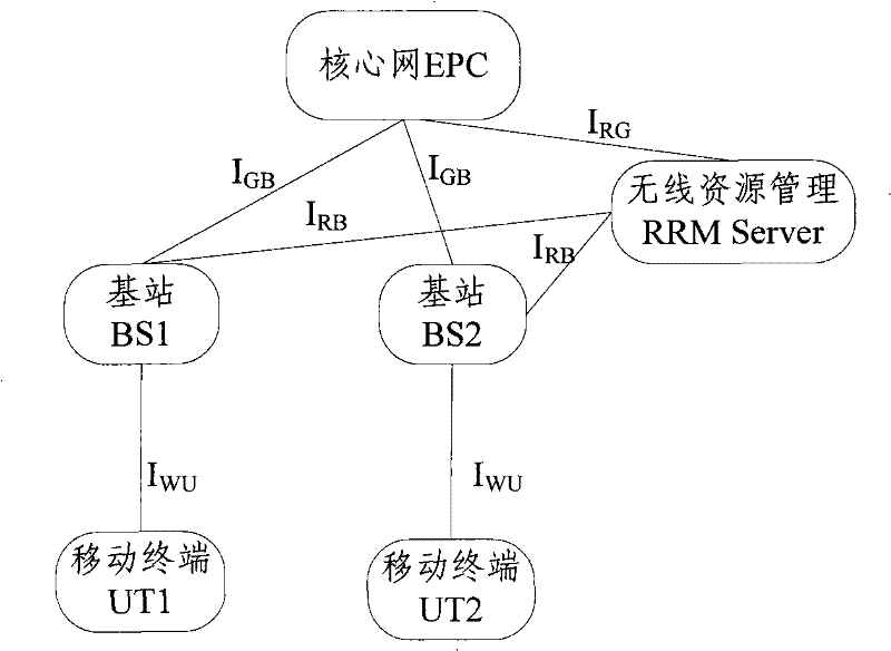
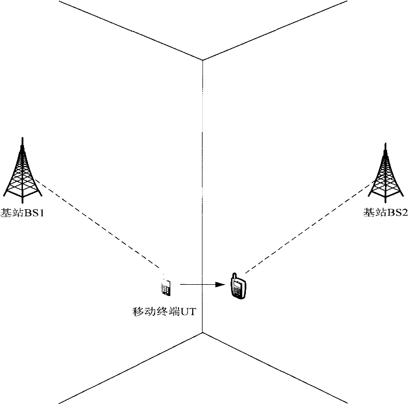
[0067] see image 3 , in this embodiment, there is no subordinate relay of the base station in the network, the base station BS1 is the source node for the initial attachment of the mobile terminal UT, the base station BS2 is the target node of the mobile terminal UT, BS1, BS2, BS3 ( image 3 not shown) form a set of downlink nodes, and in this embodiment both the target node and the downlink node are base stations. When the mobile terminal UT moves from left to right, that is, from the coverage of BS1 to the coverage of BS2, the handover process of UT is as follows: Figure 4 shown, including the following steps:

[0068] Step 401: The mobile terminal initially attaches to BS1. When the terminal moves to the cell boundary and triggers the handover threshold, it will send a measurement report to the RRM Server. The measurement report contains a list of candidate target nodes {BS1, BS2, BS3, BS4...}.

[0069] Step 402: The RRM Server selects the optimal node from the candidat...

Embodiment 2

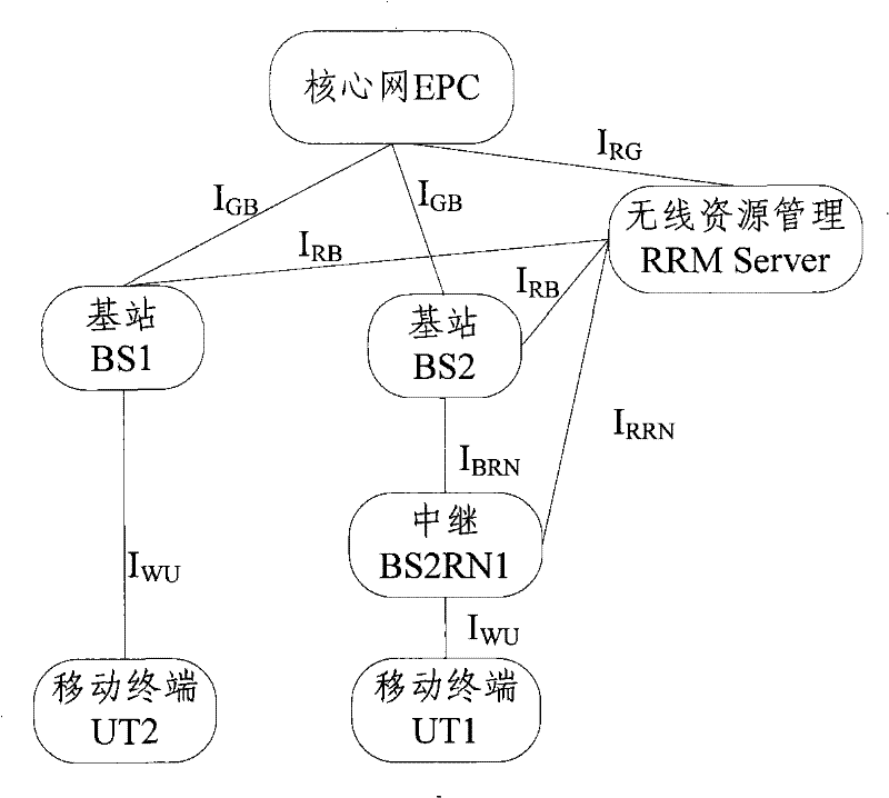
[0096] see Figure 5 , in this embodiment, there is a subordinate relay of the base station in the network, the base station BS1 is the source node for the initial attachment of the mobile terminal UT and has no subordinate relay, BS2RN1 and BS2RN2 are the subordinate relays of the base station BS2, and BS2RN2 is the target node of the mobile terminal UT , BS1, BS2, RN2, BS3 ( Figure 5 not shown in ) to form a downlink node set. When the mobile terminal UT moves from left to right, that is, from the coverage of BS1 to the coverage of BS2, the handover process of UT is as follows: Image 6 shown, including the following steps:

[0097] Step 601: The mobile terminal UT initially attaches to BS1. When the mobile terminal UT moves to the cell boundary, a handover threshold is triggered, and a measurement report will be sent to the RRM Server. The measurement report contains a list of candidate target nodes {BS1, BS2RN1, BS2RN2, BS3...}.

[0098] Step 602: The RRM Server selec...

Embodiment 3

[0126] see Figure 7 , in this embodiment, there are relays subordinate to the base station in the network, BS1RN1 and BS1RN2 are the relays subordinate to the base station BS1, BS1RN2 is the source node for the initial attachment of the mobile terminal UT, and the base station BS2 is the target node of the mobile terminal UT and has no subordinate relays Next, BS1RN1, BS1RN2, BS2, and BS3 form a downlink node set. When the mobile terminal UT moves from left to right, that is, from the coverage of BS1 to the coverage of BS2, the handover process of UT is as follows: Figure 8 shown, including the following steps:

[0127] Step 801: The mobile terminal UT initially attaches to BS1RN2. When the UT moves to the cell boundary, a handover threshold is triggered, and a measurement report will be sent to the RRM Server. The measurement report contains a list of candidate target nodes {BS1RN1, BS1RN2, BS2, BS3...}.

[0128] Step 802: The actions performed are similar to the step 60...


PUM


Abstract

The invention discloses a method for mobile terminal to realize channel switch, which includes the following steps: during the switch preparation stage, RRM Server ensures a target node and a down node-set, and the down node-set begins to provide downstream data for the mobile terminal during the switch preparation stage; during the switch stage, the mobile terminal switches the uplink into the target node assured by RRM Server or mobile terminal, then the downstream data is sent by down node-set; after the switch, the down node focus the node release resources except the target node, and thetarget node provides up-down service for mobile terminal. The invention also discloses a system and a RRM Server for mobile terminal to realize channel switch, using the method, system and RRM Servercan reduce drop-calls and resource occupation of mobile terminal in switch process, and realize continuous receiving of downstream data in the whole switch process by mobile terminal, and improves transmission service quality of mobile terminal.

Description

technical field [0001] The present invention relates to a technology for cell switching by a mobile terminal, in particular to a method, a system and a wireless resource management node for a cell switching by a mobile terminal. Background technique [0002] In the 3GPP Long Term Evolution (LTE) system, when a mobile terminal performs cell handover, it usually includes two stages of handover preparation and handover execution. In the handover preparation stage: the mobile terminal monitors the wireless channel environment in real time. When the wireless channel environment changes, the mobile terminal will send a measurement report to the source base station; The target base station sends a handover request message, requiring the target base station to reserve corresponding resources for the mobile terminal; if the target base station has corresponding idle resources, or the resources required by the mobile terminal can be freed through certain scheduling, the target base st...

Claims


Application Information

Patent Timeline
Patent Type & Authority Patents(China)
IPC IPC(8): H04W72/04
Inventor 王文清张娟赵国胜
Owner DATANG MOBILE COMM EQUIP CO LTD
Learn More