Humidification system for fuel cell

一种燃料电池、加湿系统的技术,应用在燃料电池、燃料电池助剂、运输燃料电池技术等方向,能够解决风机负载增加、压力降增加等问题

Active Publication Date: 2009-03-11
HYUNDAI MOTOR CO LTD
View PDF0 Cites 16 Cited by
  • Summary
  • Abstract
  • Description
  • Claims
  • Application Information

AI Technical Summary

Problems solved by technology

In addition, conventional membrane humidifiers have disadvantages because, in the high current region, the pressure drop increases and the fan load increases as the airflow increases

Method used


Image

  • Humidification system for fuel cell
  • Humidification system for fuel cell
  • Humidification system for fuel cell

Examples


Embodiment Construction

[0034] Reference will now be made in detail to the preferred embodiments of the present invention, examples of which are illustrated in the accompanying drawings, like reference numerals referring to like elements throughout. The embodiments are described below in order to explain the present invention by referring to the figures.

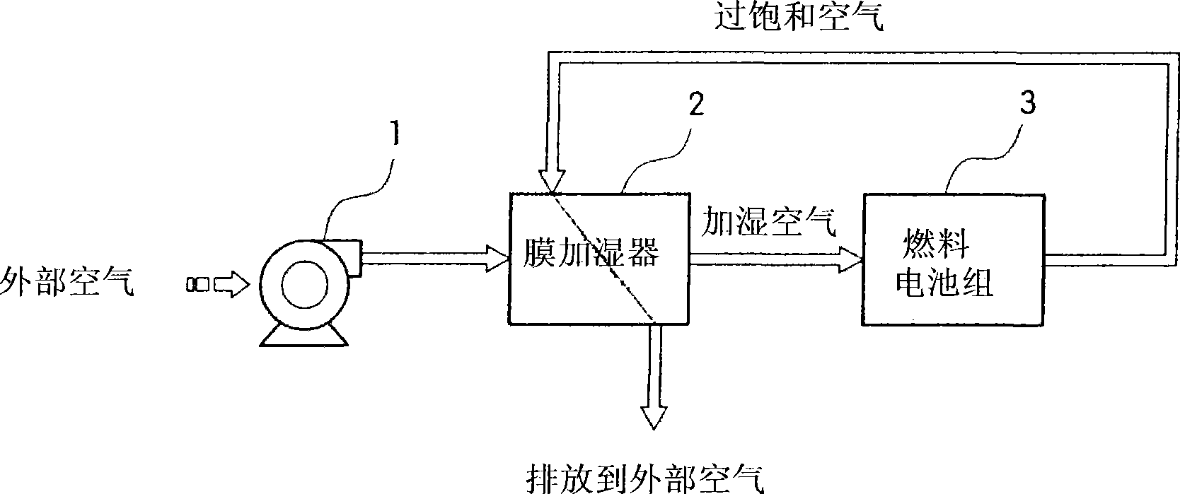
[0035] The present invention provides a humidification system for a fuel cell capable of adjusting the amount of humidification of dry air according to the amount of current generated by a fuel cell stack or the output of a vehicle.

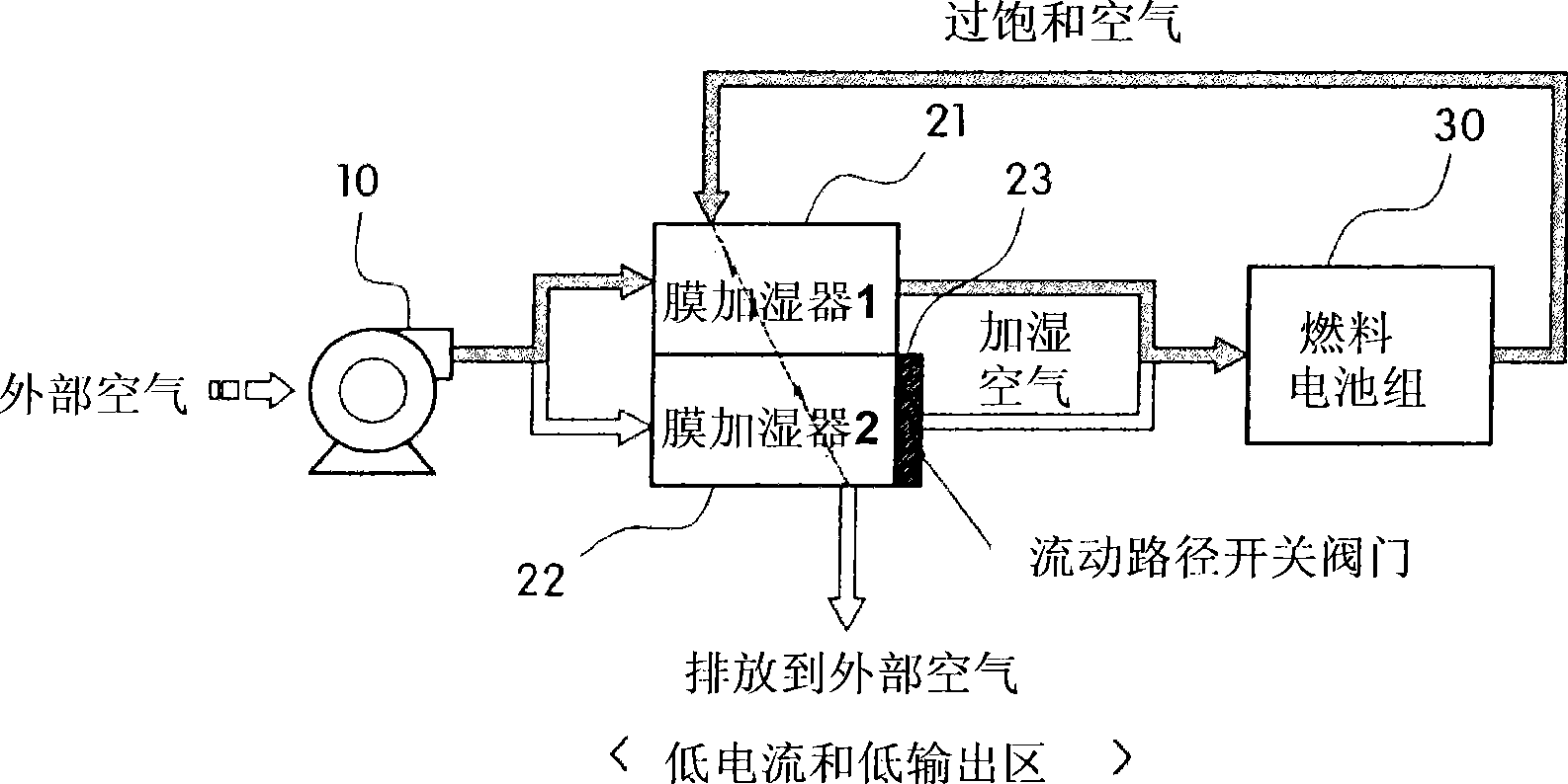
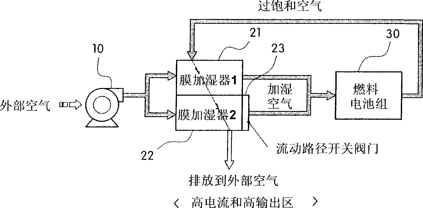
[0036] figure 2 is a view showing the configuration and operation state of the fuel cell humidification system according to the present invention in a low current and low output region, and image 3 is a view showing the configuration and operating state of the fuel cell humidification system according to the present invention in a high current and high output region.

[0037] As shown in the figure, the humidifica...


PUM


Abstract

The present invention provides a humidification system for a fuel cell, in which a plurality of membrane humidifiers employing hollow fiber membranes of different kinds having different diameters and pore sizes, or having different numbers of hollow fiber membranes is selectively used according to the amount of current generated from a fuel cell stack or a vehicle output, thus adjusting the humidification amount for dry air to be supplied to a fuel cell stack, and preventing the flooding phenomenon caused at a cathode and the starvation phenomenon in which the air supply is insufficient at the cathode.

Description

technical field [0001] The invention relates to a fuel cell humidification system. More particularly, the present invention relates to a fuel cell humidification system that can adjust the humidity of dry air to be supplied to a fuel cell stack. Background technique [0002] A fuel cell system is a power generation system that directly converts the chemical energy of fuel into electrical energy. [0003] A fuel cell system generally includes a fuel cell stack for power generation, a fuel supply system for supplying fuel (hydrogen) to the fuel cell stack, and an air supply system for supplying oxygen in the air to the fuel cell stack, oxygen being an electrochemical reaction The required oxidant, and a heat and water management system for removing the heat of reaction of the fuel cell stack from the fuel cell system and controlling the operating temperature of the fuel cell stack. [0004] The fuel cell system having the above-described configuration generates electricity t...

Claims


Application Information

Patent Timeline
Patent Type & Authority Applications(China)
IPC IPC(8): H01M8/04
CPCH01M2250/20Y02T90/32B01D63/046H01M8/04149Y02E60/50B01D2313/18B01D63/02Y02T90/40H01M8/04B01D63/031
Inventor 全义植
Owner HYUNDAI MOTOR CO LTD
Why Eureka
Try Eureka