Chip stacker having outer support for truss and method for turning truss with the support

A truss, material accumulation technology, applied in the field of truss support

Inactive Publication Date: 2009-03-25
ANDRITZ AG
View PDF0 Cites 2 Cited by
  • Summary
  • Abstract
  • Description
  • Claims
  • Application Information

AI Technical Summary

Problems solved by technology

These forces limit the length of the truss and thus the size of the chip pile that can be formed by the chip stacker

Method used


Image

  • Chip stacker having outer support for truss and method for turning truss with the support
  • Chip stacker having outer support for truss and method for turning truss with the support

Examples


Embodiment Construction

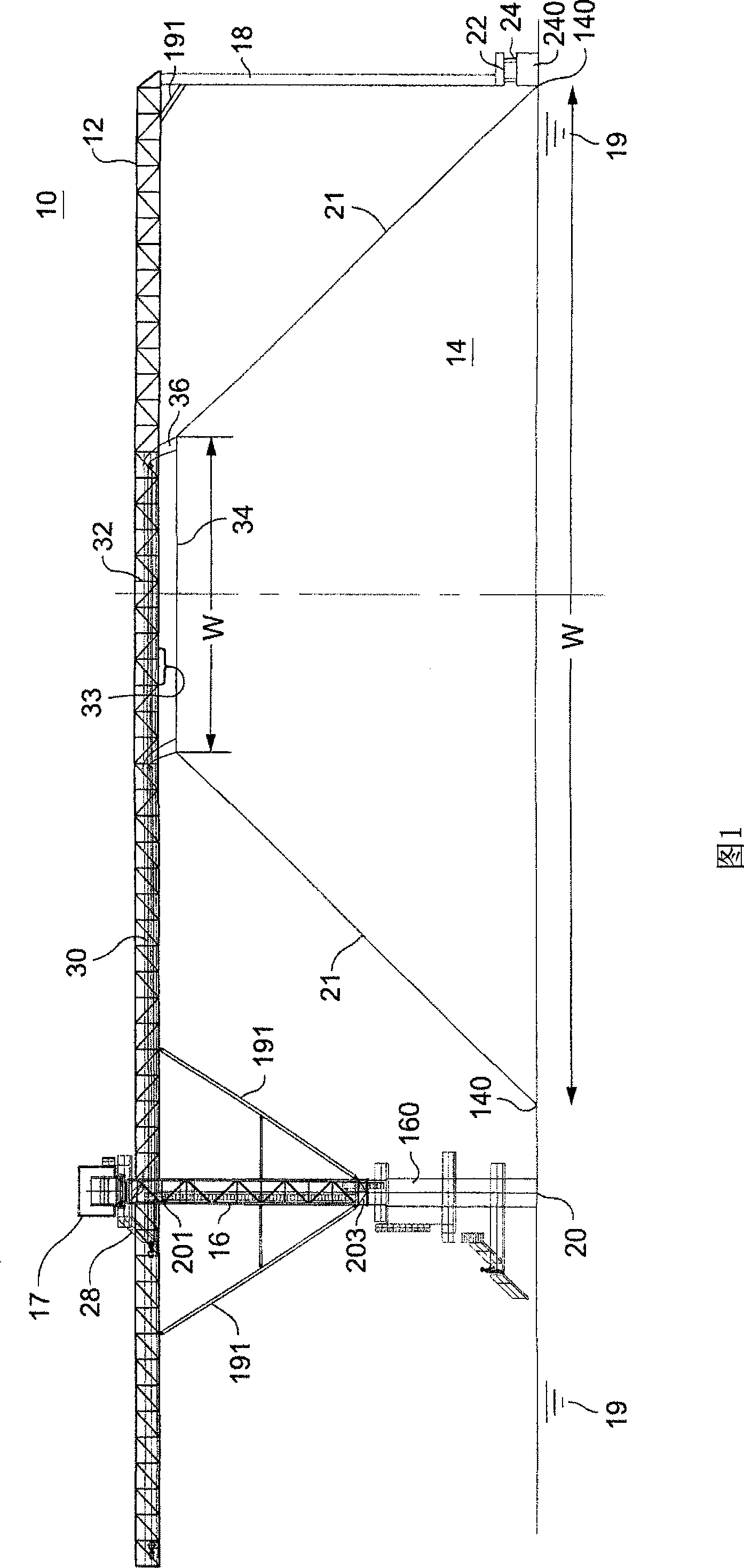
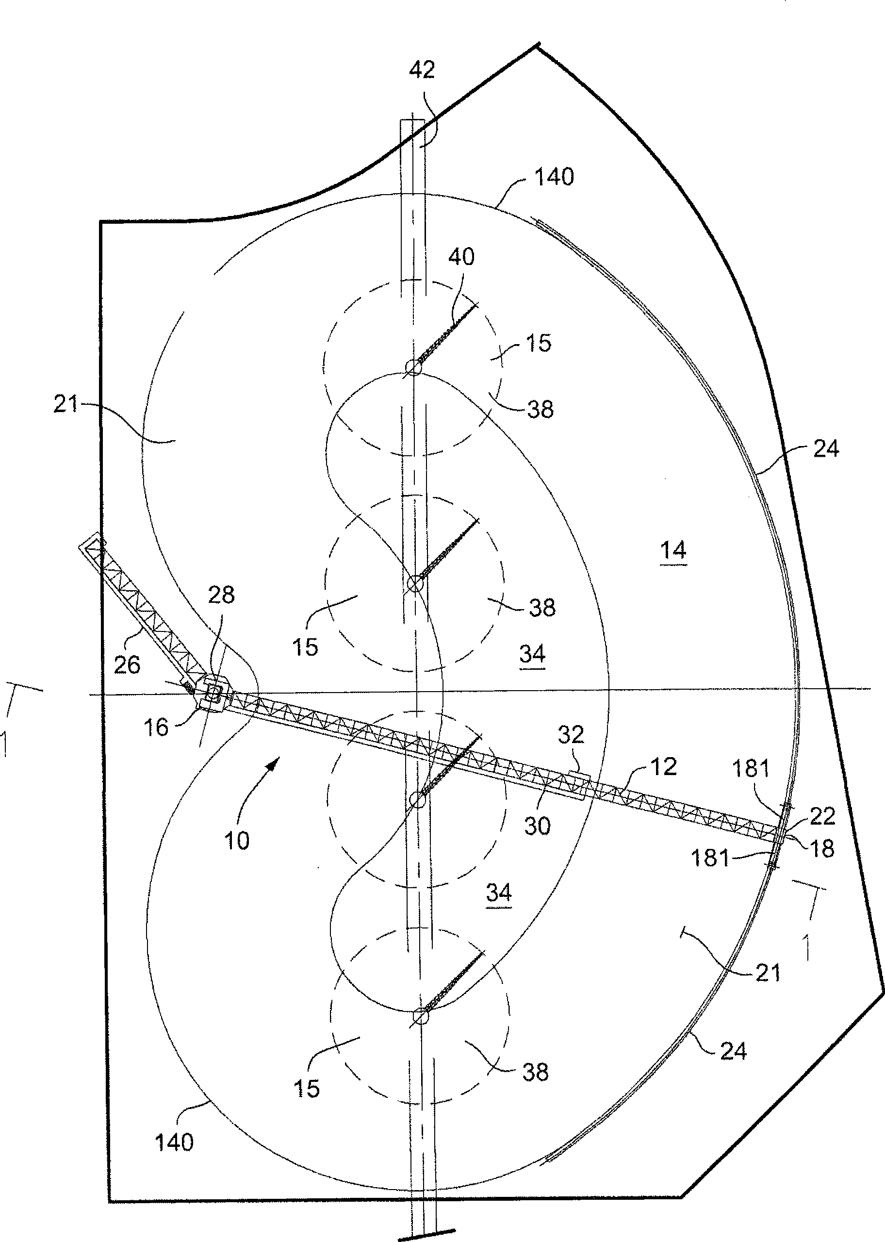
[0016] FIG. 1 is a side view of a chip stacker 10 having an upper horizontal truss 12 extending above a chip pile 14 . figure 2 It is a top view of the sawdust stacker, the sawdust pile and the piled up sawdust recovery system 15.

[0017] The truss 12 is supported by a central strut 16 and outer struts 18 . The struts 16 , 18 are located at opposite ends of the truss 12 . The center post 16 is the pivot of the truss. The truss moves in an arc around the central strut. The arc may be a complete circle or an arc forming a part of a circle. As the truss pivots about the central strut, the outer struts 18 move with the truss in an arc.

[0018] The truss 12 may be a lattice structure, such as a lattice truss or other weight-reducing, high-strength support structures. Similarly, struts 16, 18 may be formed from a lattice structure or a reduced weight, high strength support structure. The central pillar can also be a full or partial concrete column 160 . The center pillar 16...


PUM


Abstract

A material stacking device including: an elevated truss supported at opposite ends by first and second pillars, the first pillar includes a pivot allowing the truss to pivot about the location of the first pillar and the second pillar moving in an arc as the truss turns about the first pillar, and a material conveyor extending at least part way along the truss and discharging material to be deposited to an upper section of a material pile below the truss.

Description

[0001] cross reference [0002] This application claims the benefit of US Provisional Patent Application Serial No. 60 / 971,619, filed September 12, 2007, the entire contents of which are incorporated herein by reference. technical field [0003] This invention relates to wood chip or other material stacking machines for forming large piles of wood chips and other particulate or granular materials. In particular, the present invention relates to supports for trusses in chip stacking installations. Background technique [0004] Wood processing plants, such as manufacturing plants, convert wood into wood chips. Wood chips are stored in large piles. From these chip piles the chips are conveyed, for example, to a digester or beater which converts the chips into wood pulp. Chips stored in heaps are often referred to as piled chips. [0005] A conventional chip stacking device (stacker) conveys chips or other materials to a chip pile to form a chip pile. Chip stackers are typi...

Claims


Application Information

Patent Timeline
IPC IPC(8): B65G65/28
Inventor 布鲁斯·柯克帕特里克耶内·莱赫滕迈基伯纳德·奥康纳
Owner ANDRITZ AG
Why Eureka
Try Eureka