Projection type image display device

An image display device and projection optics technology, which is applied to projection devices, instruments, food ingredients containing gas, etc., can solve the problems that the reflection of the cover plate cannot be ignored, the imaging performance deteriorates, and the focus distance is short.

Active Publication Date: 2009-05-13
SEIKO EPSON CORP
View PDF2 Cites 26 Cited by
  • Summary
  • Abstract
  • Description
  • Claims
  • Application Information

AI Technical Summary

Problems solved by technology

[0005] However, the above-mentioned projection optical system has an ultra-wide angle of view, so the focal length becomes extremely short, and the diameter of the beam near the optical axis becomes narrow. rough beam
Therefore, when a parallel plane cover is arranged near the concave reflector in order to protect the concave reflector, the angle of light incident on the peripheral portion of the cover becomes very shallow due to the wide-angle projection, and the imaging performance is affected. Deterioration, reflection at the surface of the cover becomes impossible to ignore
In addition, in the projection optical system using such a concave mirror, the optical path converges near the focal point or near the exit pupil position of the concave mirror. Therefore, it is preferable to arrange the cover plate at a position slightly away from the converging part from the viewpoint of safety. However, As the parallel plane cover is separated from the converging position, the size of the cover tends to increase, and problems arise in terms of the strength of the cover and the method of supporting it.

Method used


Image

  • Projection type image display device
  • Projection type image display device
  • Projection type image display device

Examples


no. 1 Embodiment approach

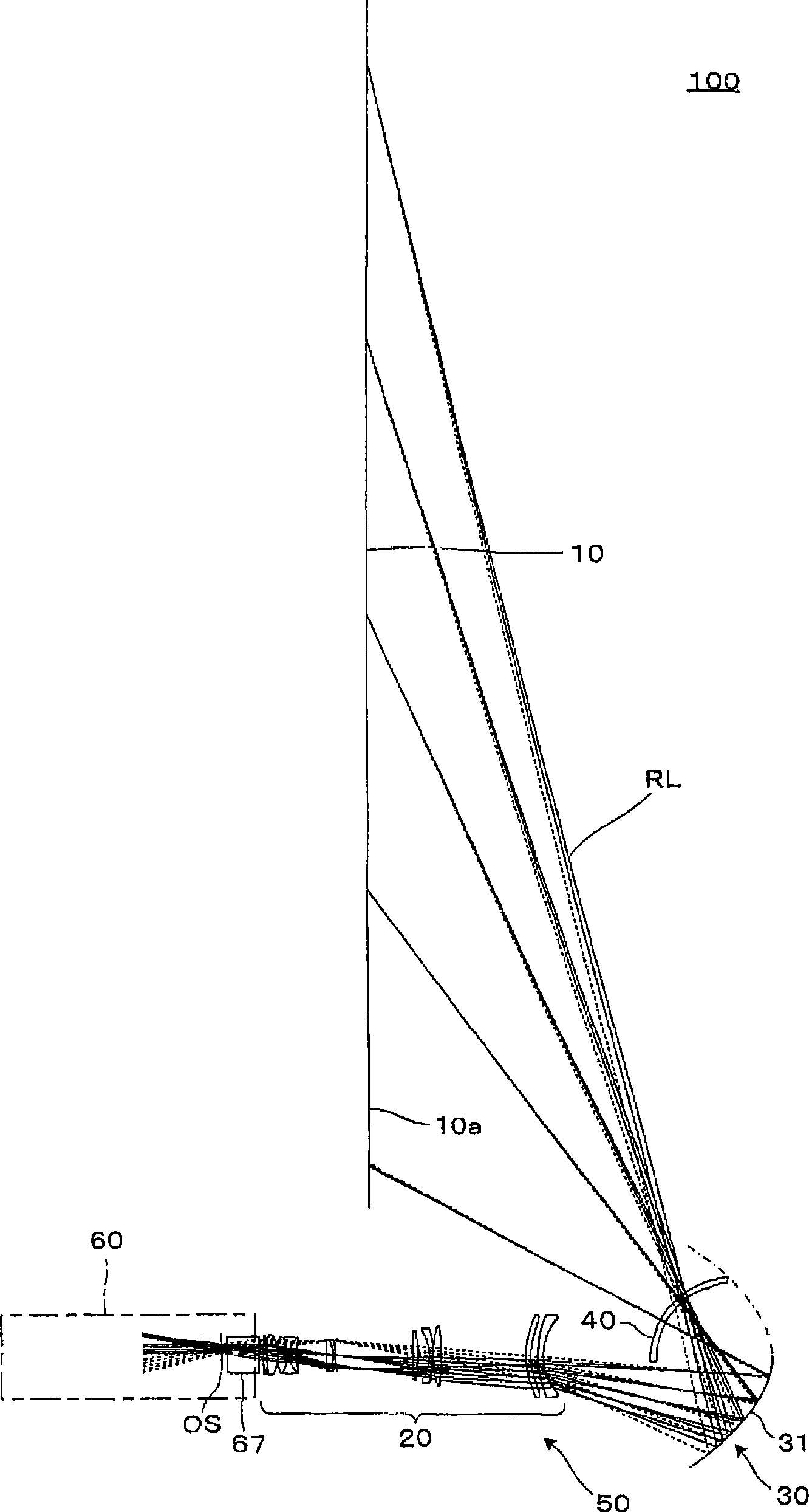
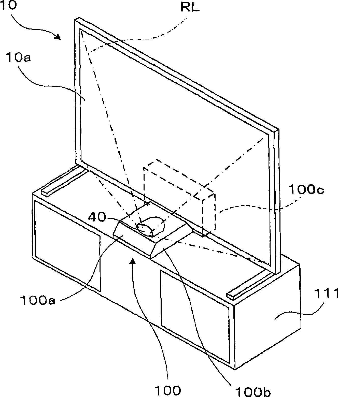
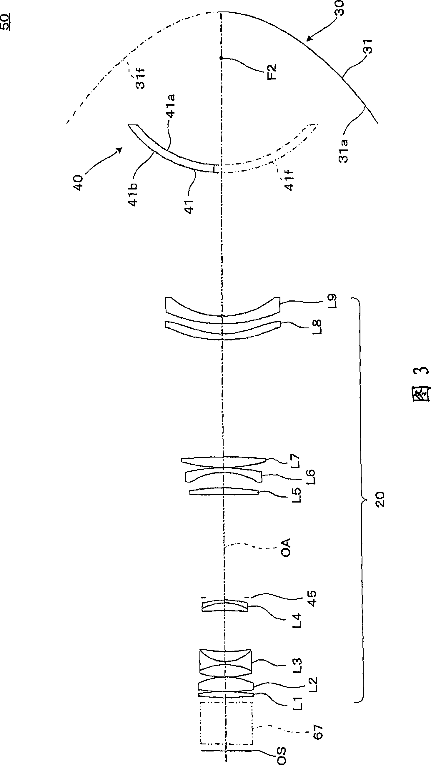
[0067] figure 1 It is a side view showing main parts of an optical system constituting the projection type image display device according to the first embodiment of the present invention. figure 2 It is a perspective view explaining the appearance of the projection type image display device.

[0068] The projection type image display device 100 in this embodiment includes a screen 10 , a projection optical system 50 , and an image forming optical unit 60 . Here, the screen 10 is installed on the enlargement side of the projection optical system 50 , that is, at the rear of the optical path, and the image forming optical unit 60 is installed on the reduction side of the projection optical system 50 , that is, at the front of the optical path. In addition, in figure 1 In the figure, only a part of the image forming optical unit 60 , that is, the cross dichroic prism 67 is shown, and the details of the remaining parts are omitted. In addition, for the projection optical syste...

no. 2 Embodiment approach

[0144] Figure 7 It is a side view showing the main part of the optical system constituting the projection type image display device according to the second embodiment, and FIG. 8 is a diagram illustrating the configuration of the projection optical system in the projection type image display device. In addition, FIG. 9 is an enlarged view illustrating a main part of the projection optical system.

[0145] The projection type image display device 200 of this embodiment is for figure 1 The image display device obtained by modifying the projection type image display device 100 of the first embodiment shown in Fig.

[0146] The projection type image display device 200 in this embodiment includes: a screen 10, a projection optical system 250, and an image forming optical unit 60; and the second refractive optical unit 240.

[0147] The first refractive optical unit 220 includes a first lens L1, a second lens L2, a third lens L3, a fourth lens L4, a fifth lens L5, a sixth lens L...

no. 3 Embodiment approach

[0207] Figure 10 It is a side view showing the main part of the optical system constituting the projection type image display device according to the third embodiment, and FIG. 11 is a diagram illustrating the configuration of the projection optical system in the projection type image display device. In addition, FIG. 12 is an enlarged view illustrating a main part of the projection optical system.

[0208] The projection type image display device 300 of this embodiment is for figure 1 The image display device obtained by modifying the projection type image display device 100 of the first embodiment shown in Fig.

[0209] The projection type image display device 300 in this embodiment includes: a screen 10, a projection optical system 350, and an image forming optical unit 60; and the second refractive optical unit 340.

[0210] The first refractive optical unit 320 includes a first lens L1, a second lens L2, a third lens L3, a fourth lens L4, a fifth lens L5, a sixth lens...


PUM


Abstract

The present invention provides a projection type image display device which is corresponding with the requirement of wide angle. The projection type image display device can reduce the deterioration of imaging capability and the reflection at the surface and is provided with a small-size cover plate. A refractive optical surface (40b) of the amplifying side of concavo-convex lens (41) at the amplifying side is provided with a convex surface shape projected to the amplifying side, so the second refractive optical part (40) can function as a protecting cover of projection optical system (50) when the projection is executed with a wide visual angle. Thus the thickness of concavo-convex lens (41) is approximately uniform, and furthermore the concavo-convex lens (41) is set to a convex surface shape projected to the amplifying side, so the surface area as protecting cover can be reduced, and the effect to imaging can be reduced. Additionally, as the concavo-convex lens (41) is formed to a concentric sphere shaped dome that the curvature center of lens surface is collocated adjacently to the position of exit pupil of reflective optical part (30), the effect caused by the concavo-convex lens (41) to the imaging effect can be reduced.

Description

technical field [0001] The present invention relates to a projection type image display device incorporating a projection optical system for projecting an image formed by a liquid crystal panel or the like on a screen. Background technique [0002] As a projection optical system for disposing the projection device near the screen and projecting its image on the screen, there is a device having a refractive optical system including a plurality of lenses arranged on the reduction side, and a refraction optical system arranged on the enlargement side. The concave reflector that makes the optical path turn back to the side, enlarges and approaches the projection on the screen (for example, patent documents 1 and 2). [0003] Patent Document 1: JP-A-2004-258620 [0004] Patent Document 2: JP-A-2006-235516 [0005] However, the above-mentioned projection optical system has an ultra-wide angle of view, so the focal length becomes extremely short, and the diameter of the beam near...

Claims


Application Information

Patent Timeline
Patent Type & Authority Applications(China)
IPC IPC(8): G03B21/00G03B21/14A23L21/10A23L29/231A23L29/238A23L29/256A23L29/269
CPCA23V2002/00A23L2/54A23L1/304A23L1/0532A23L1/06A23L29/256A23L21/10A23L33/16A23V2250/11A23V2250/50364A23V2250/507A23V2250/5086A23V2250/1578A23V2250/16
Inventor 峯藤延孝
Owner SEIKO EPSON CORP
Why Eureka
Try Eureka