Optical processing structure for a digital light processing projection device

a technology of light processing and projection device, which is applied in the direction of optical radiation measurement, instruments, spectrophotometry/monochromators, etc., can solve the problems of adding to the cost, the combination module of dlp projectors is assembled, and the aforementioned wavelength shift of s and p polarized lights, so as to reduce the load designed for the lens, the effect of light weight and cheaper pri

Inactive Publication Date: 2008-04-10
DELTA ELECTRONICS INC
View PDF2 Cites 15 Cited by
  • Summary
  • Abstract
  • Description
  • Claims
  • Application Information

AI Technical Summary

Benefits of technology

[0011]One objective of this invention is to provide a light processing structure used in a digital light processing (DLP) projection device, wherein the DLP projection device uses both a color separation mirror and a color wheel as a color separation system, as well as using a color-combining prism assembly comprising two triangular prisms as a color combination system. Since the volume of the color-combining prism assembly is small, the required back focus length of the projection lens is shorter than that of the prior arts so that the loading designed for the lens can be reduced to a lighter weight and a cheaper price.

Problems solved by technology

One of the existing problems in conventional technologies is that the wavelength shift of the aforementioned S and P polarized lights while color separation are inconsistent with that of the S and P polarized lights while color combination.
Another existing problem in the conventional technologies is that the color combination module of 3-chip DLP projectors is assembled by an X-prism in conjunction with three TIR prisms.
Consequently, the prisms are larger in volume and weight, thereby adding to the cost.
As a result, there are more difficulties in designing the lens.

Method used


Image

  • Optical processing structure for a digital light processing projection device
  • Optical processing structure for a digital light processing projection device
  • Optical processing structure for a digital light processing projection device

Examples


Embodiment Construction

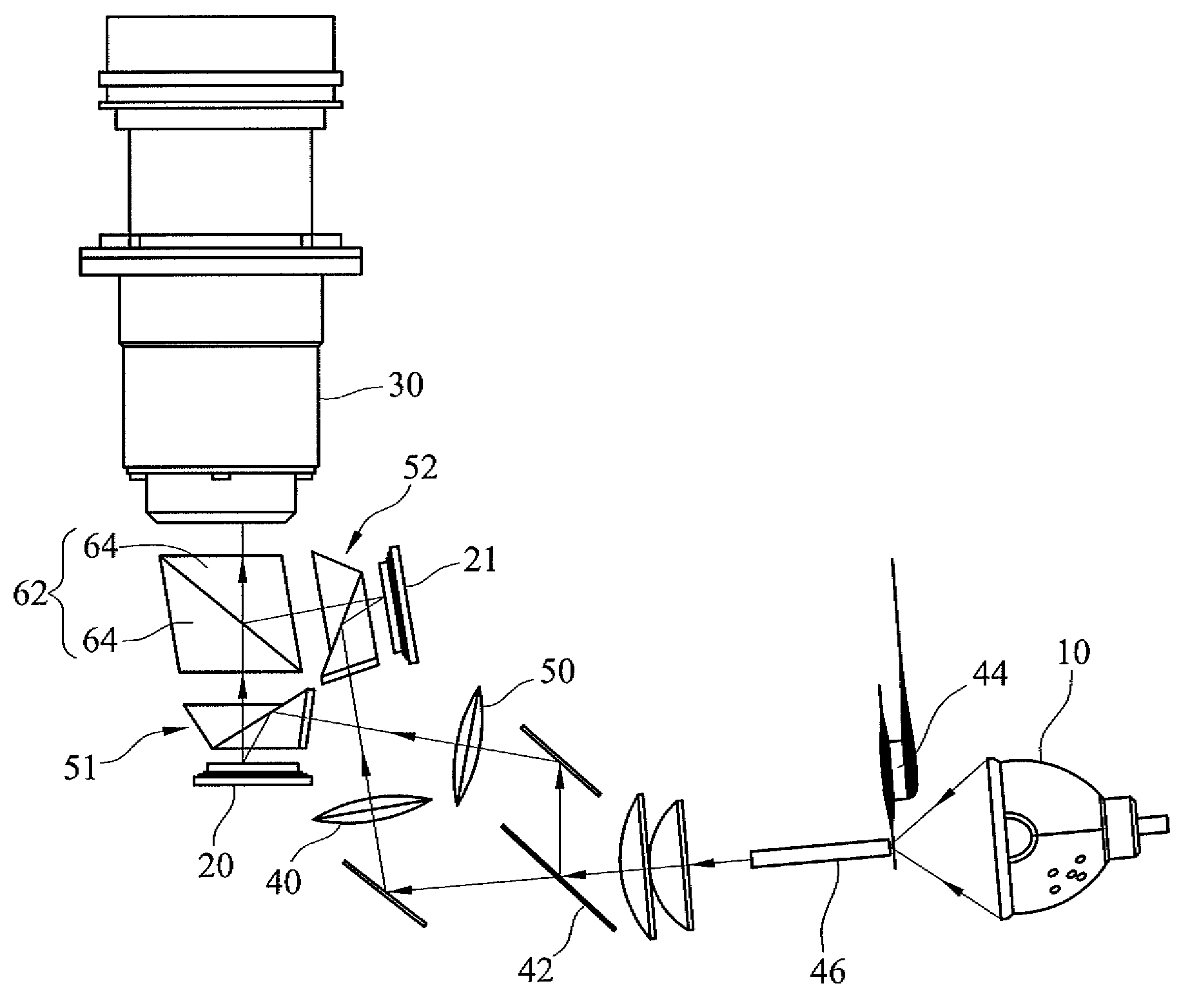
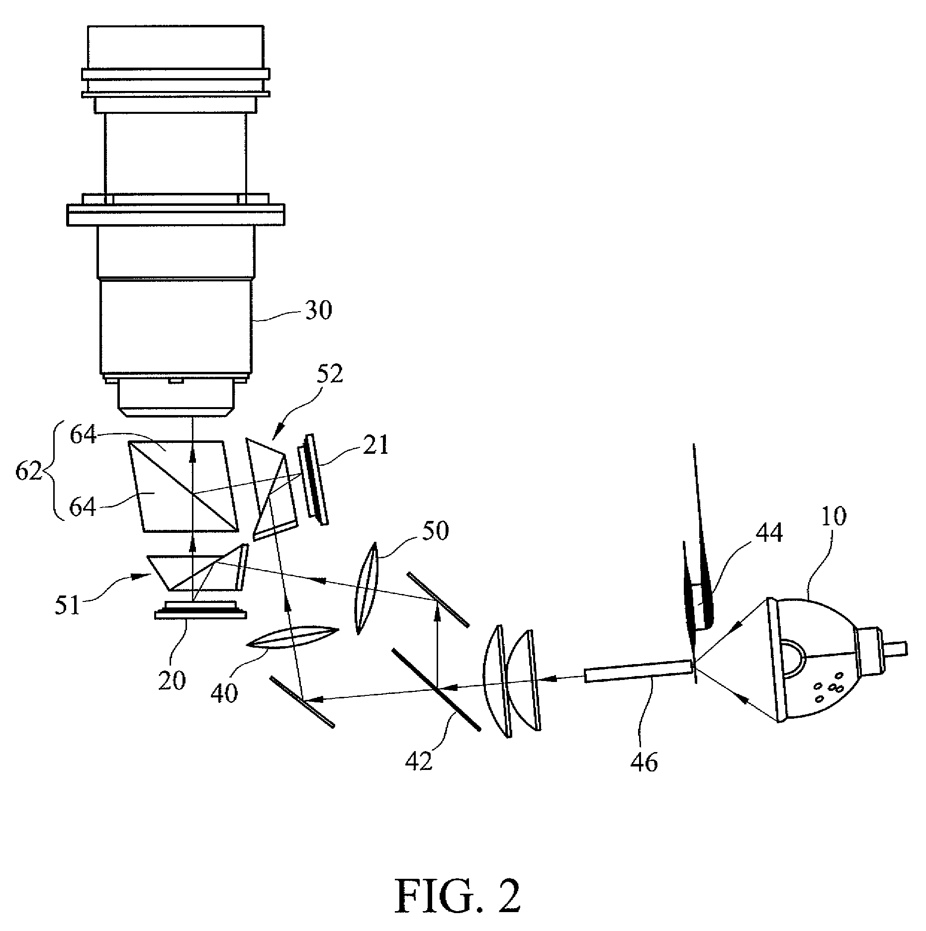
[0021]FIG. 2 shows an embodiment of a light processing structure of a DLP projection device, wherein the DLP projection device comprises a light source 10, a plurality of DMDs (shown as two digital micro-mirror devices 20, 21 in the figure), a projection lens 30 and the light processing structure of the invention. The light processing structure comprises a color separation mechanism, a reflecting mechanism and a color combination mechanism.

[0022]In detail, the color separation mechanism comprises at least one color separation device adapted for splitting the incident light emitted by the light source 10 into a plurality of incident sub-light beams. In a real embodiment, the color separation device can be a color separation mirror 42. According to the different types of light sources and different requirements for separating light, optical coating layers within the color separation mirror are adapted for splitting the incident light into a plurality of differently colored incident su...


PUM


Abstract

A light processing structure for a digital light processing (DLP) projection device is disclosed. The DLP projection device comprises a plurality of digital micro-mirror devices (DMDs). The optical processing structure comprises a color separation mechanism, a reflecting mechanism and a color combination mechanism, wherein the color separation mechanism utilizes dichroic mirror(s) and a color wheel for splitting light beams into individual colors. The reflecting mechanism includes a plurality of TIR prisms corresponding to the DMDs, respectively. The color combination mechanism utilizes a color-combining prism assembly in which two triangular prisms are assembled with each other. The mentioned mechanism uses a shorter back focal length for the projection lens, thereby reducing the light processing structure and enhancing product quality.

Description

[0001]This application claims priority to Taiwan Patent Application No. 095137122 filed on Dec. 11, 2006; the disclosures of which are incorporated herein by reference in their entirety.CROSS-REFERENCES TO RELATED APPLICATIONS[0002]Not applicable.BACKGROUND OF THE INVENTION[0003]1. Field of the Invention[0004]The present invention relates to a light processing structure for a digital light processing (DLP) projection device; specifically, it relates to a light processing structure for a DLP projection device with a plurality of digital micro-mirror devices (DMD).[0005]2. Descriptions of the Related Art[0006]FIG. 1 shows a schematic diagram of a digital light-processing projector of Taiwan patent application number 93101928. The application was filed by the applicant of this invention on Jan. 29, 2004. The digital light processing projector mainly comprises a color combination module 200, a light source 300, a color separation module 400, three digital micro-mirror devices 500R, 500G...

Claims


Application Information

Patent Timeline
Patent Type & Authority Applications(United States)
IPC IPC(8): G03B21/28G03B21/00
CPCG03B21/28
Inventor CHEN, HSI-CHAOHUANG, JUNEJEI
Owner DELTA ELECTRONICS INC
Why Eureka
Try Eureka