Multi-frequency antenna

A multi-frequency antenna and antenna technology, which is applied in antennas, antenna arrays, antenna supports/mounting devices, etc., can solve the problems of reducing the installation space of antennas and the difficulty of meeting requirements for multi-frequency antennas

Inactive Publication Date: 2013-05-08
FUDING PRECISION COMPONENTS SHENZHEN +1
View PDF5 Cites 0 Cited by
  • Summary
  • Abstract
  • Description
  • Claims
  • Application Information

AI Technical Summary

Problems solved by technology

The antenna integrates the antennas used in wireless wide area network and wireless local area network, which relatively reduces the installation space of the antenna, and at the same time, each antenna still has good performance. However, sometimes in order to achieve better application results, it is necessary to make the antenna work in Three or more application networks, the multi-frequency antenna that only supports two application networks is difficult to meet the requirements

Method used


Image

  • Multi-frequency antenna
  • Multi-frequency antenna
  • Multi-frequency antenna

Examples


Embodiment Construction

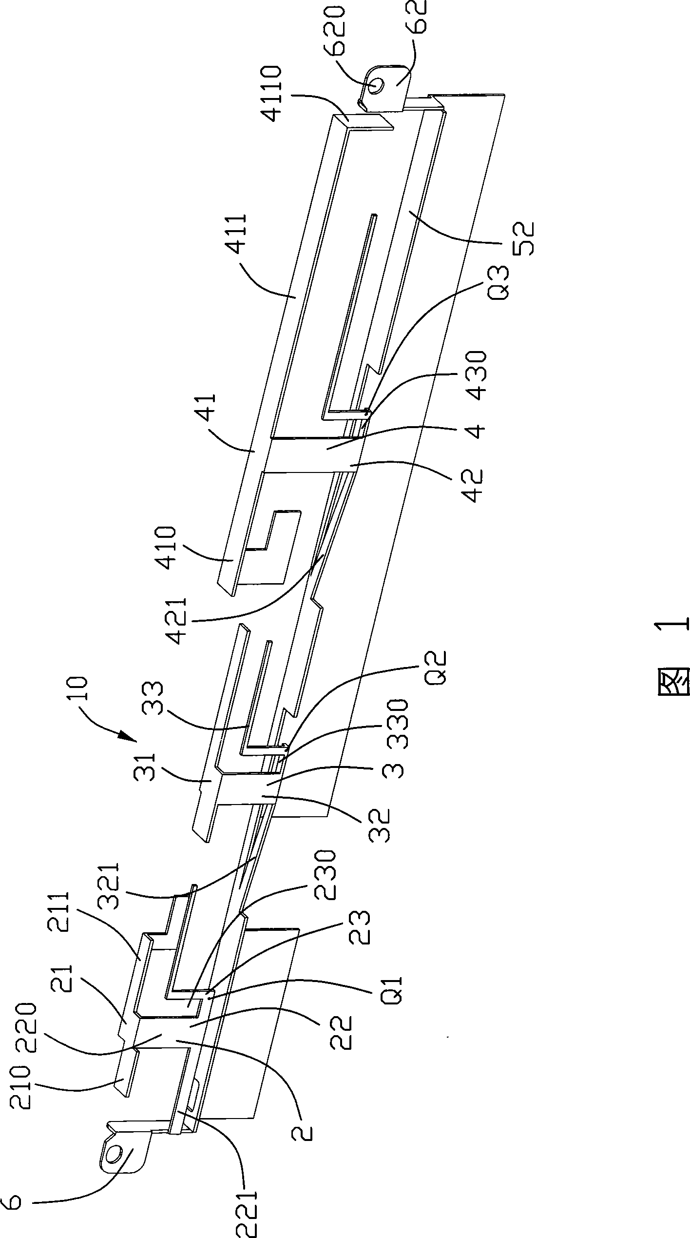
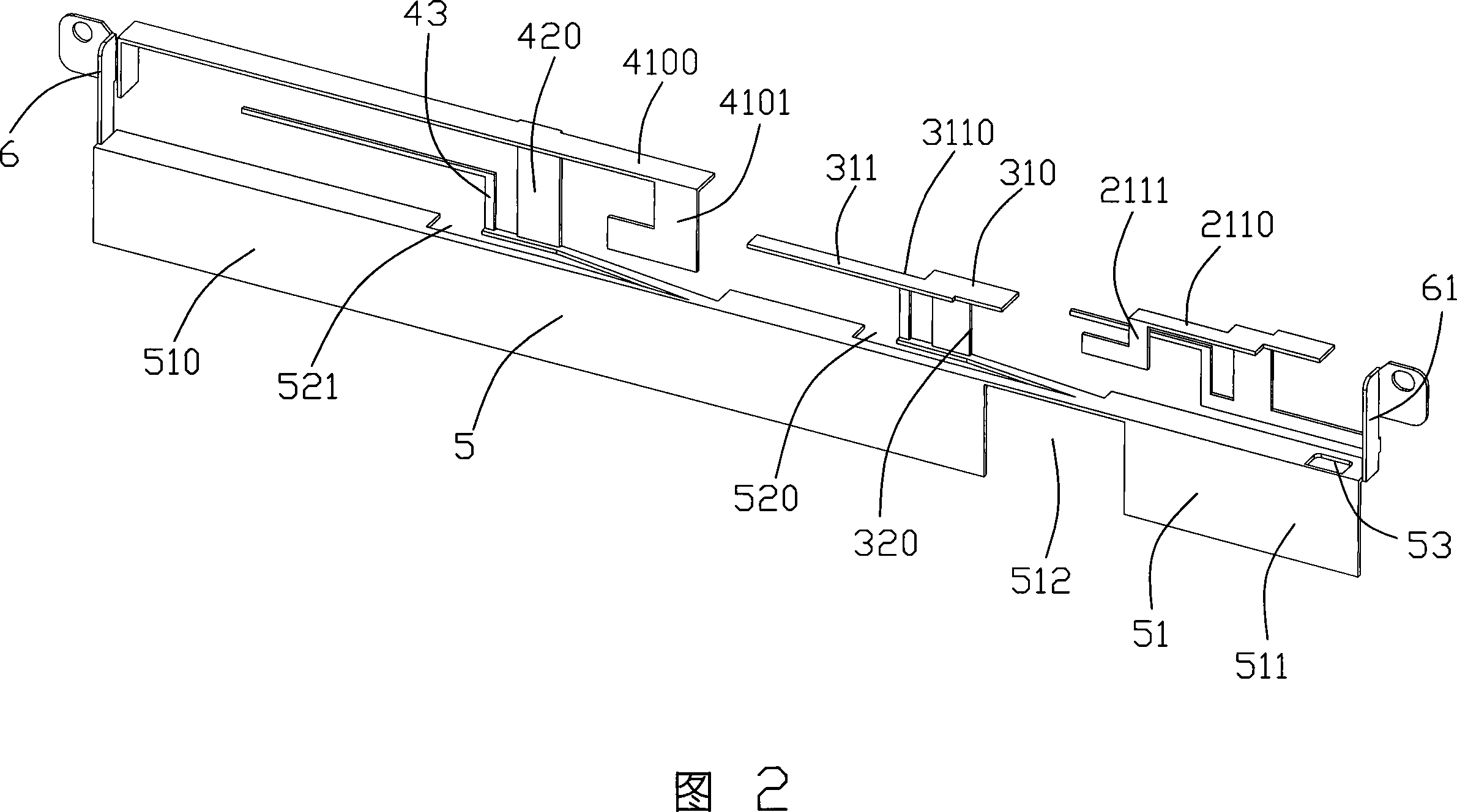
[0014] Such as figure 1 and figure 2 As shown, it is a perspective view of different angles of a preferred embodiment of the present invention. In this embodiment, the multi-frequency antenna 10 of the present invention is formed by bending and cutting a metal sheet, which includes a first antenna 2, a second antenna 3, a third antenna 4, a grounding part 5, a mounting part 6 and three signal lines (not shown), the first antenna 2 , the second antenna 3 and the third antenna 4 are located on the same side of the ground portion 5 and arranged along a lengthwise direction.

[0015] The grounding portion 5 includes a horizontal grounding portion 52 and a vertical grounding portion 51 perpendicular to the horizontal grounding portion 52 . The vertical ground portion 51 is formed with a longer rectangular first ground plate 510 and a shorter rectangular second ground plate 511 , and a gap 512 is formed between the first ground plate 510 and the second ground plate 511 . The hor...


PUM


Abstract

The invention discloses a multi-frequency antenna (10), which comprises a first antenna (2), a second antenna (3) and a third antenna (4); the first antenna (2) and the second antenna (3) are used for Worldwide Interoperability for Microwave Access and a wireless local area network, and the third antenna (4) used for a wireless wide area network, wherein, the first antenna, the second antenna andthe third antenna are made of a sheet metal.

Description

【Technical field】 [0001] The invention relates to an antenna, in particular to a multi-frequency antenna for portable electronic devices such as notebook computers. 【Background technique】 [0002] With the rapid development of communication technology and miniaturization, an important factor must be taken into consideration, that is, the design of the antenna must be correspondingly miniaturized. [0003] Planar Inverted-FAntenna PIFA is a commonly used small antenna suitable for communication terminals such as mobile phones and notebook computers. It adapts to the trend of miniaturization and design simplification of electronic devices, as well as the requirement of antenna miniaturization. One advantage of this type of antenna is that it is easy to achieve dual-band, which can effectively reduce the space occupied by the antenna and the manufacturing cost. Another advantage is that the performance of the antenna is easy to adjust under different working environments and w...

Claims


Application Information

Patent Timeline
Patent Type & Authority Patents(China)
IPC IPC(8): H01Q21/00H01Q21/28H01Q5/00H01Q13/08H01Q1/22H01Q5/30H01Q5/328
Inventor 洪振达柯云龙谷柏冈
Owner FUDING PRECISION COMPONENTS SHENZHEN
Why Eureka
Try Eureka