Flight object

An object, trailing edge technology used in the field of flying objects

Inactive Publication Date: 2009-05-20
SILVERLIT TOYS MANUFACTORY +1
View PDF0 Cites 3 Cited by
  • Summary
  • Abstract
  • Description
  • Claims
  • Application Information

AI Technical Summary

Problems solved by technology

However, known flying objects of this type have certain disadvantages

Method used


Image

  • Flight object
  • Flight object
  • Flight object

Examples


Embodiment Construction

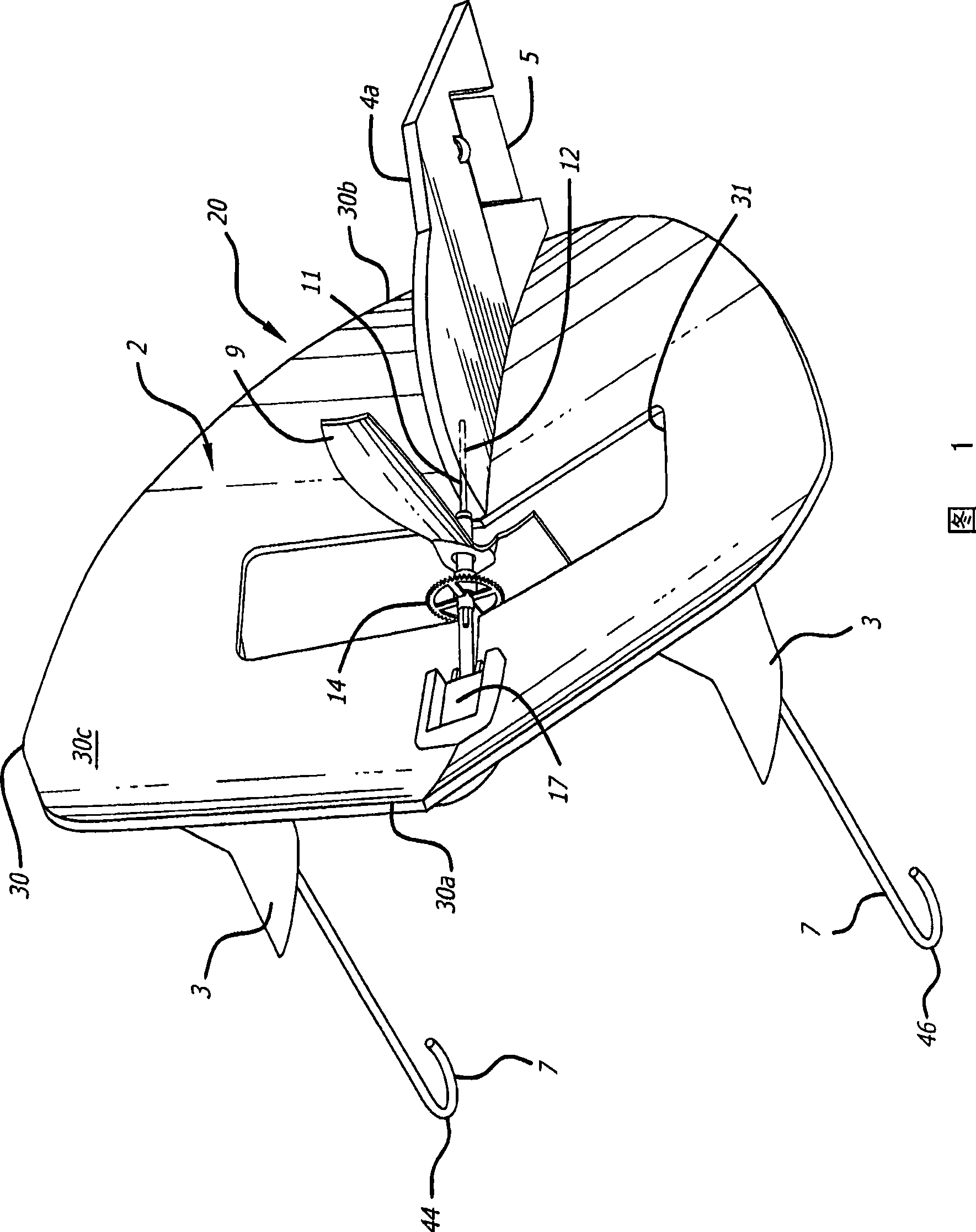
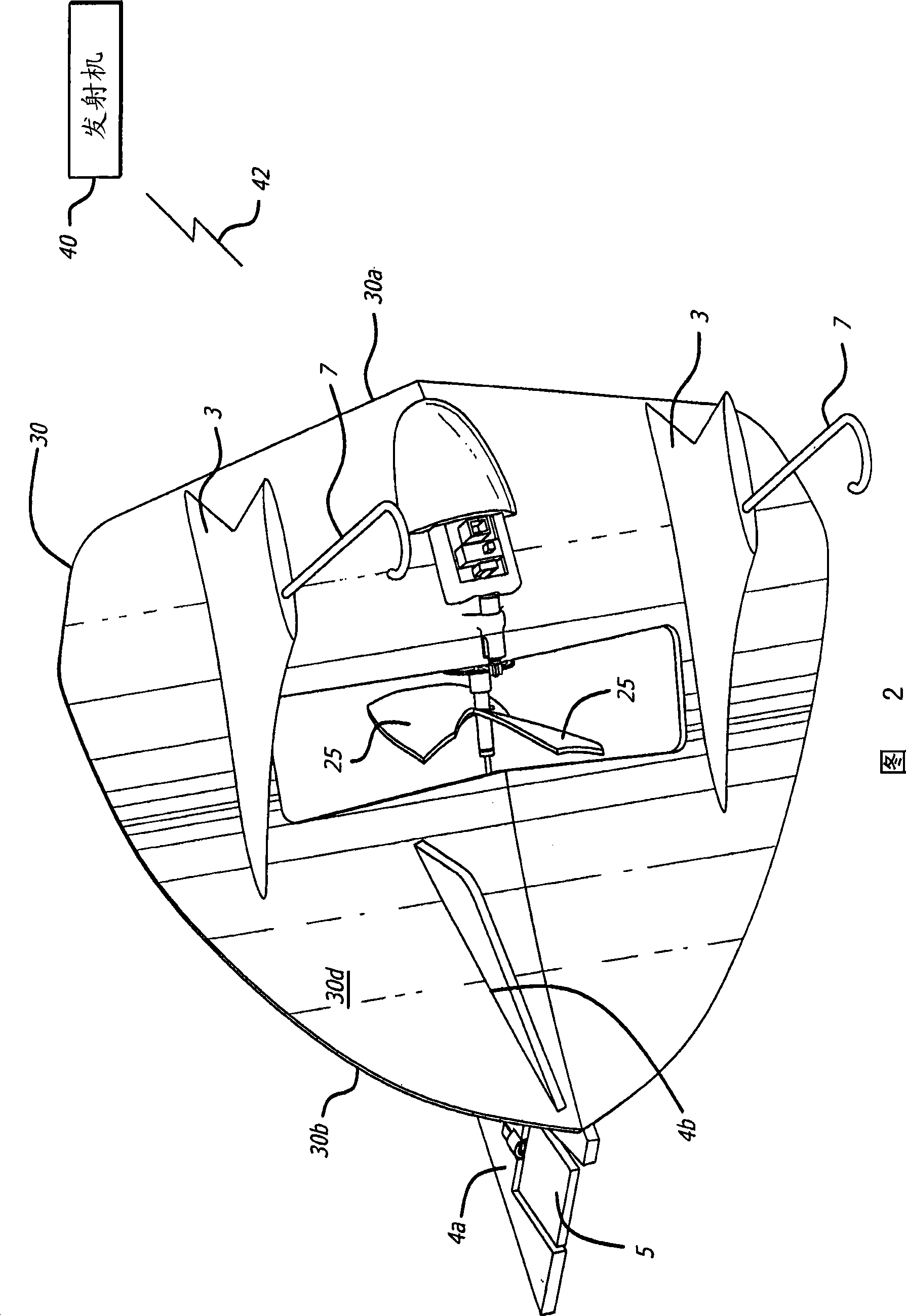
[0037] The flying object 20 includes a wing 30, wherein the wing 30 has a leading edge 30a and a trailing edge 30b and an upper surface 30c and a lower surface 30d between the leading edge 30a and the trailing edge 30b. Such as Figure 9 As shown in , the wing 30 comprises common sections 1 and 2 between a leading edge 30a and a trailing edge 30b. Such as Figure 9 As shown in a-9c, the upper surface 30c has a curved shape such that it is generally concave from the leading edge portion 30a of the upper surface 30c to the middle portion 30e of the wing (where parts 1 and 2 join). The lower surface 30d has a curvilinear shape such that it is generally convex from the leading edge portion 30a of the surface to the middle portion 30e of the wing.

[0038] With respect to a generally horizontal flight line, the slope from leading edge 30a to inwardly curved portion 30f in a direction towards central portion 30e is greater than the portion from inwardly curved portion 30f to central...


PUM


Abstract

The invention relates to an aircraft wing for a flyer. The aircraft wing is provided with a leading edge, a trailing edge and an upper surface and a lower surface between the leading edge and the trailing edge, wherein a part between the leading edge and the trailing edge is provided with the upper surface in the shape of a curve; a part from the leading edge part of the upper surface to the middle part of the upper surface is provided with a concave shape; the lower surface takes the shape of a curve like this: the part from the leading edge part of the upper surface to the middle part of the upper surface is provided with a convex shape; a propeller which is used for generating the propulsion for flying forwards is received into a transverse orifice on the surface of the aircraft wing; and a paddle of the propeller rotates in a plane which transversely cuts a straight line between the leading edge and the trailing edge of the surface.

Description

technical field [0001] The present invention generally relates to a flying object, such as a toy flying device or a toy airplane. In particular, the present invention relates to a wing-like surface shape structure capable of sustained flight. Background technique [0002] The flight characteristics of such a flying object are determined by the shape of the object or some parts of the object. The object can be powered, or in more cases have a glider structure. Factors such as weight, airframe, and wing shape and size determine its flight characteristics. Furthermore, such a flying object can optionally be manned by a person with or without radio control. However, known flying objects of this type have certain disadvantages. [0003] Flying objects are well known as complex machines which are potentially unstable and thus difficult to control, requiring more experience in order to safely maneuver such flying objects without mishaps. Contents of the invention [0004] Th...

Claims


Application Information

Patent Timeline
Patent Type & Authority Applications(China)
IPC IPC(8): A63H27/00A63H27/18A63H27/24
Inventor A·J·M·范德罗斯泰恩
Owner SILVERLIT TOYS MANUFACTORY
Why Eureka
Try Eureka