Air processing unit based on air blast thermal recovery and energy step utilization

An air handling unit, heat recovery technology, applied in heat recovery systems, energy recovery systems using air flow as shielding, ventilation and heating, etc., can solve problems such as increased system energy consumption, low dew point, energy quality waste, etc. Achieve the effect of simple and reasonable system structure, increase dew point temperature, and reduce system energy consumption

Inactive Publication Date: 2009-05-20
HARBIN INST OF TECH
View PDF3 Cites 15 Cited by
  • Summary
  • Abstract
  • Description
  • Claims
  • Application Information

AI Technical Summary

Problems solved by technology

[0003] The purpose of the present invention is to solve the problem that existing air-conditioning units with centralized air supply cannot utilize cascaded energy, resulting in a waste of energy quality; for air-conditioning units with a part of the air that bears the humidity load, the dew point achieved by air cooling treatment is lower, reducing The coefficient of performance of the refrigerator is improved; the reheating air supply, while raising the dew point temperature achieved by the air cooling process, causes the cold heat to be offset and increases the energy consumption of the system. Air Handling Unit Utilized

Method used


Image

  • Air processing unit based on air blast thermal recovery and energy step utilization
  • Air processing unit based on air blast thermal recovery and energy step utilization

Examples


specific Embodiment approach 1

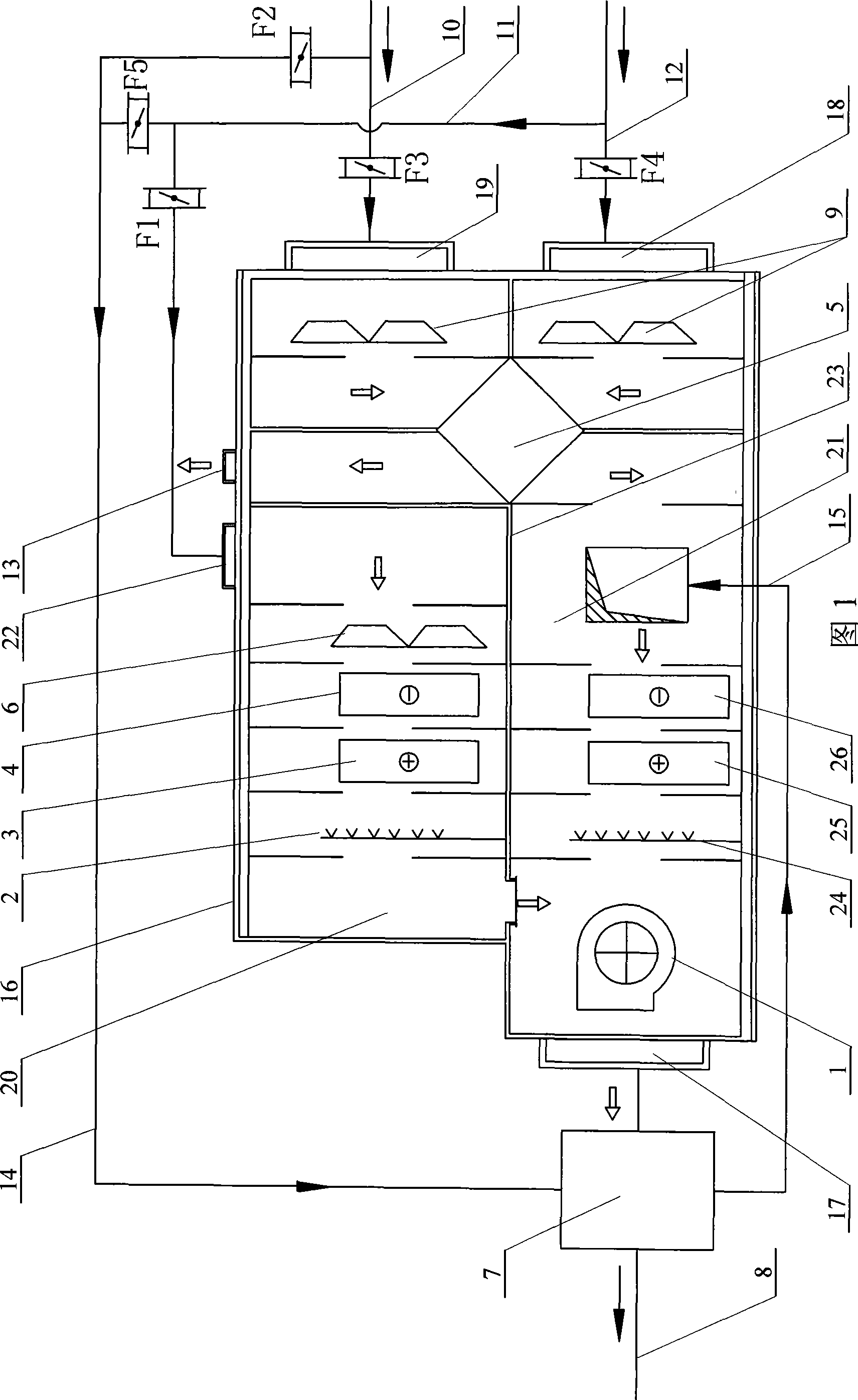
[0006] Specific Embodiment 1: (See Fig. 1) This embodiment includes blower 1, exhaust air heat recovery device 5, air supply heat recovery device 7, air supply duct 8, fresh air inlet duct 10, return air duct 11, and exhaust duct 12. Exhaust air outlet 13, first pipeline 14, second pipeline 15, box body 16, air outlet 17, first air inlet 18, second air inlet 19, upper processing unit 20, lower processing Unit 21, return air inlet 22, partition 23, first air volume regulating valve F1, second air volume regulating valve F2, third air volume regulating valve F3, fourth air volume regulating valve F4 and fifth air volume regulating valve F5, air outlet 17 is fixed on the outlet side of the box body 16, the blower 1 is arranged at the outlet in the box body 16, the first air inlet 18 and the second air inlet 19 are fixed side by side on the inlet side of the box body 16, and the heat exhausted The recycler 5 is fixed on the inside of the inlet of the box body 16, and the exhaust p...

specific Embodiment approach 2

[0007] Specific embodiment two: (referring to Fig. 1) present embodiment has increased two primary-end filters 9, and two primary-end filters 9 are respectively arranged on two air inlets of exhaust air heat recovery device 5 in casing 16 front side. Others are the same as in the first embodiment.

specific Embodiment approach 3

[0008] Embodiment 3: (see FIG. 1 ) In this embodiment, a return air filter 6 is added, and the return air filter 6 is arranged at the inlet end of the upper processing unit 20 in the box body 16 . Others are the same as in the second embodiment.

[0009] The filter added in the above-mentioned Embodiment 2 and Embodiment 3 is used to filter out impurities in the incoming air, so as to make the air fresher.

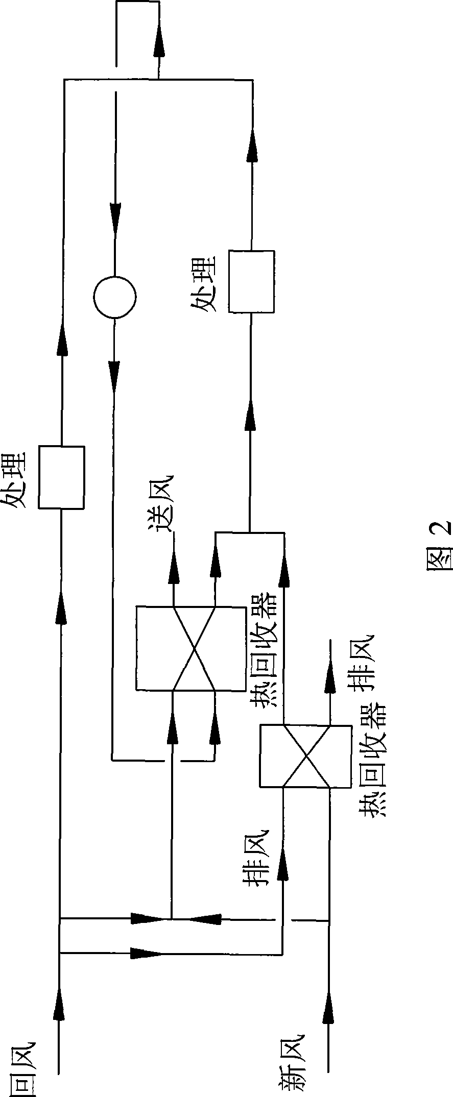
[0010] Air treatment method: (see Figure 1 and Figure 2) If the fresh air volume is sufficient, the fifth air volume regulating valve F5 is closed. A part of the fresh air enters the air supply heat recovery device 7 through the second air volume regulating valve F2 for supply air heat recovery, and another part of the fresh air enters the exhaust air heat recovery section through the third air volume regulating valve F3 for exhaust air heat recovery, and then is combined with the recovered heat Part of the fresh air is mixed and treated together; the return air enters th...


PUM


Abstract

The invention discloses an air-handling unit based on air blast heat recovery and graded use of energy, which relates to an air-handling unit. The air-handling unit aims to solve the problems that the prior air-conditioning unit for centralized processing of blast air can not realize graded use of the energy, the dew point achieved by air cooling treatment is low, and reheated blast air is easy to cause counteraction of cold and heat, so that the energy consumption of the system is increased. The air-handling unit is as follows: an air outlet is communicated with an inlet of an air blast channel of an air blast and heat recovery device; a blast pipe is communicated with an outlet of the air blast channel of the air blast and heat recovery device; and one end of a second pipe is communicated with an outlet of an air blast and heat recovery pipe of the air blast and heat recovery device, and the other end of the second pipe is communicated with the initial end of a lower handling unit. Due to arrangement of the air blast and heat recovery device, the air-handling unit has a simple and reasonable systemic structure and low manufacturing cost. The air-handling unit effectively solves the problem of counteraction of the cold and the heat, reduces energy consumption of the system and improves the dew-point temperature of air cooling treatment through the air blast and heat recovery device, so as to improve the performance coefficients of the refrigerating system.

Description

technical field [0001] The invention relates to an air handling unit. Background technique [0002] As a common equipment in the air conditioning system, the air handling unit has been widely used in various central air conditioning systems. There are many problems in the operation process of the existing air handling (air conditioning) units. The main aspects are as follows: 1. Air-conditioning units with centralized air supply cannot utilize energy in stages, resulting in a waste of energy quality; 2. Air-conditioning units with part of the air bearing the humidity load, the dew point achieved by air cooling treatment is low , which reduces the coefficient of performance of the refrigerator; 3, the reheating air supply, while raising the dew point temperature achieved by the air cooling treatment, it causes the offset of cold and heat, and increases the energy consumption of the system. Contents of the invention [0003] The purpose of the present invention is to solve...

Claims


Application Information

Patent Timeline
Patent Type & Authority Applications(China)
IPC IPC(8): F24F3/044F24F3/14F24F3/16F24F12/00
CPCY02B30/16Y02B30/563Y02B30/56
Inventor 姜益强姚杨柴永金牛福新
Owner HARBIN INST OF TECH
Why Eureka
Try Eureka